Slipform paver concrete compaction vibrator

A slipform paver and concrete technology, which is applied to roads, road repairs, roads, etc., can solve the problems of slump deformation of structures, uniform and compact vibrating rods, and low slump, so as to eliminate damage and stabilize the mold mechanism. Effect

Active Publication Date: 2013-05-15
JIANGSU SIMING ENG MACHINERY
View PDF5 Cites 4 Cited by
  • Summary
  • Abstract
  • Description
  • Claims
  • Application Information

AI Technical Summary

Problems solved by technology

[0002] Most of the existing slip-form pavers use plug-in vibrating rods for compact molding. The slump of the required concrete must be stable within a reasonable range. If the slump is too high, the paved structures will collapse. The slump is too low, the workability of the concrete is poor, it is difficult for the vibrating rod to compact it evenly, and the structure is not full, internal potholes and other defects

Method used


Image

  • Slipform paver concrete compaction vibrator
  • Slipform paver concrete compaction vibrator

Examples


Embodiment Construction

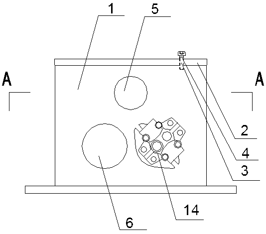
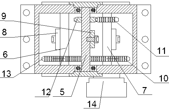
[0013] Such as figure 1 , 2 As shown, the present invention comprises box body 1, and the upper end of box body 1 is an opening, and the opening of box body 1 upper end is provided with cover plate 2, and described cover plate 2 is provided with vent hole 3, and the vent hole 3 is threadedly connected with Vent screw 4.

[0014] A high-speed shaft 5 arranged longitudinally is arranged in the center of the box body 1, a low-speed shaft 6 arranged longitudinally is arranged in the box body 1 below the left side of the high-speed shaft 5, and a low-speed shaft 6 arranged longitudinally is arranged in the box body below the right side of the high-speed shaft 5. 1 is provided with a longitudinally arranged drive shaft 7, the low-speed shaft 6 and the drive shaft 7 are symmetrically arranged with the high-speed shaft 5 as the center of symmetry, and the middle parts of the low-speed shaft 6 and the drive shaft 7 are respectively fixedly connected with a first eccentric block 8, Th...


PUM


Abstract

The invention relates to a cement concrete compaction external vibrator, especially to a slipform paver external vibrator for compulsive compaction of cement concrete during continuous pouring of kerbs, side ditches and other structures. The concrete compaction vibrator comprises a box body. A longitudinally arranged high speed shaft is disposed at a central position inside the box body. A low speed shaft and a drive shaft are arranged on two sides of the high speed shaft symmetrically. The middle parts of the low speed shaft and the drive shaft are respectively in fixed connection with a first eccentric block. The middle part of the high speed shaft is in fixed connection with a second eccentric block. The low speed shaft, the high speed shaft and the drive shaft are provided with transmission gears. One side of the box body is equipped with a driving hydraulic motor that drives the drive shaft to rotate. With a stable structure, the slipform paver concrete compaction vibrator provided in the invention can remove the concrete adhered to a template lower surface so as to ensure a smooth surface of a concrete structure.

Description

technical field [0001] The invention relates to an external vibrator for cement concrete compaction, in particular to an external vibrator used for forced compaction of cement concrete by a slip form paver in the process of continuously pouring curb stones, side ditches and other structures. Background technique [0002] Most of the existing slip-form pavers use plug-in vibrating rods for dense molding. The required concrete slump must be stable within a reasonable range. If the slump is too high, the paved structure will collapse. Falling deformation; the slump is too low, the workability of the concrete is poor, it is difficult for the vibrating rod to compact it evenly, and the structure is not full, internal potholes and other defects. Contents of the invention [0003] The purpose of the present invention is to solve the above problems and provide a concrete compacting vibrator for a slipform paver that can force compact cement concrete during continuous pouring of st...

Claims


Application Information

Patent Timeline
Patent Type & Authority Applications(China)
IPC IPC(8): E01C19/48
Inventor 赵国普何慧国龚国芳郝名洪
Owner JIANGSU SIMING ENG MACHINERY
Why Eureka
Try Eureka