A valve with intelligent positioning and anti-clogging

An intelligent positioning and anti-blocking technology, applied in the valve device, valve details, valve operation/release device, etc., can solve the blockage of the piezoelectric valve inlet or exhaust port, abnormal operation, damage to the intelligent valve positioner, etc. question

Active Publication Date: 2022-07-12
JIANGSU BOTWAY FLUID TECH CO LTD
View PDF0 Cites 0 Cited by
  • Summary
  • Abstract
  • Description
  • Claims
  • Application Information

AI Technical Summary

Problems solved by technology

With the increase of smoke and dust generated by heating and combustion in the industrial process, the increase of automobile exhaust emissions and other reasons, the content of particulate matter in the air continues to rise, resulting in the current pneumatic intelligent valve positioner after a period of use. Piezoelectric The air inlet or exhaust port of the valve is blocked and the work is abnormal, and the operating environment of the valve positioner and the valve is generally relatively humid, which is easy to cause damage to the internal components of the intelligent valve positioner

Method used


Image

  • A valve with intelligent positioning and anti-clogging
  • A valve with intelligent positioning and anti-clogging
  • A valve with intelligent positioning and anti-clogging

Examples


Embodiment 1

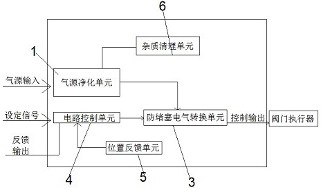
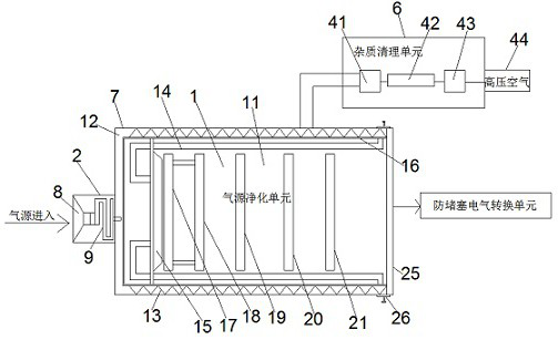
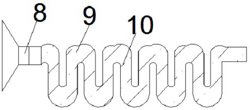
[0034] see Figure 1-8 , according to an embodiment of the present invention, a valve with intelligent positioning and anti-clogging includes a positioner and a valve actuator, the positioner includes an air source purification unit 1, and an input air source is provided on the air source purification unit 1 The air inlet 2, the air source purification unit 1 is connected to the anti-clogging electrical conversion unit 3 used to control the valve actuator, and the anti-clogging electrical conversion unit 3 is connected to a circuit control unit 4 through a control signal. The circuit control unit 4 is connected with the position feedback unit 5, the air source purification unit 1 is connected with an impurity cleaning unit 6, the air source purification unit 1 includes a purification housing 7, and the air inlet 2 is made of plastic air intake The purification shell 7 and the air inlet 2 are detachably connected, and the inner wall of the air inlet 2 close to the opening is pr...

Embodiment 2

[0036] see Figure 4 , For the purification housing 7 , one end of the purification housing 7 is provided with an internal thread groove 45 , and the air inlet 2 is screwed into the internal thread groove 45 .

[0037] Through the above scheme of the present invention, the beneficial effects are as follows: the air inlet 2 is screwed into the inner thread groove 45, so that the air inlet 2 is screwed with the purification housing 7, which is convenient for installation and easy to disassemble.

Embodiment 3

[0039] see Image 6 For the air pressure input passage 28, the connection points of the air pressure input passage 28, the air pressure output passage 29, the exhaust passage 30 and the working passage 27 are connected by arc surfaces.

[0040] Through the above-mentioned solution of the present invention, the beneficial effects are as follows: the connections of the air pressure input passage 28, the air pressure output passage 29, the exhaust passage 30 and the working passage 27 are connected by arc surfaces, so as to avoid impurities in the air passage. The corners are deposited, and a filter dust screen 34 is installed inside the air pressure input passage 28, which can block dust and effectively prevent dust from entering.


PUM


Abstract

The invention discloses a valve with intelligent positioning and anti-clogging, comprising a positioner and a valve actuator, the positioner includes an air source purification unit, and an air inlet for inputting an air source is arranged on the air source purification unit, The air source purification unit is connected to an anti-clogging electrical conversion unit for controlling the valve actuator, the anti-clogging electrical conversion unit is connected to a circuit control unit through a control signal, and the circuit control unit is connected to a position feedback unit. Beneficial effect: The drying indicator wrapped inside the absorbent cotton can absorb the moisture in the air flow, so as to keep the interior of the purification shell dry and avoid damage to the valve positioner, and during cleaning, the heating mechanism is provided to make the hot air enter the interior of the purification shell , Heat and dry the absorbent cotton, the drying indicator and the absorbent cotton, so that the absorbent cotton, the drying indicator and the absorbent cotton are in a dry working state, which ensures that the absorbent cotton and other parts can absorb moisture for a long time.

Description

technical field [0001] The invention relates to the field of valve positioning, in particular to a valve with intelligent positioning and anti-clogging. Background technique [0002] The valve positioner is the main accessory of the control valve. It uses the stem displacement signal as the input feedback measurement signal, and the controller output signal as the setting signal for comparison. When there is a deviation between the two, the output to the actuator is changed. The signal makes the actuator act, and the one-to-one correspondence between the displacement of the valve stem and the output signal of the controller is established. Therefore, the valve positioner constitutes a feedback control system with the stem displacement as the measurement signal and the controller output as the set signal. The manipulated variable of the control system is the output signal of the valve positioner to the actuator. The valve positioner that cooperates with the pneumatic actuat...

Claims


Application Information

Patent Timeline
Patent Type & Authority Patents(China)
IPC IPC(8): F16K31/02F16K31/12F15B21/048B03C3/41B03C3/45B03C3/017B01D53/26B01D46/00B01D46/12B01D50/00
CPCF16K31/02F16K31/004F16K31/12F15B21/048B03C3/41B03C3/45B03C3/017B01D50/00B01D46/12B01D53/26B01D53/261B01D46/0036B01D46/62Y02B30/70
Inventor 胡斌刘荣霞邱琳熙吴连峰张啸周游
Owner JIANGSU BOTWAY FLUID TECH CO LTD
Why Eureka
Try Eureka