Supercharge Your Innovation With Domain-Expert AI Agents!

Method for measuring the lifetime of an excited state in a sample

一种测量样本、激发态的技术,应用在测量荧光寿命的设备,测量荧光寿命,测量样本中激发态寿命的设备领域,能够解决时间测量卡死区时间长、测量率低一般重复频率、高成本等问题,达到快速且有效处理的效果

Active Publication Date: 2013-05-15
LEICA MICROSYSTEMS CMS GMBH
View PDF10 Cites 9 Cited by
  • Summary
  • Abstract
  • Description
  • Claims
  • Application Information

AI Technical Summary

Problems solved by technology

However, in addition to the high cost, such time measurement cards have the disadvantage of a particularly long dead time, so that, after excitation of the sample, they are only able to detect the arrival of the first detection pulse (first detection photon) and then after a few Being "blind" for a long period of time
Ultimately, a significant portion of the information contained in the detection light emitted from the sample remains hidden from the user
[0007] Furthermore, it is not possible to achieve a high repetition rate for the excitation pulses and, therefore, to perform frequent measurements within one measurement cycle
Practical achievable measurement rates are well below typical repetition rates of commercially available pulsed lasers

Method used


Image

  • Method for measuring the lifetime of an excited state in a sample
  • Method for measuring the lifetime of an excited state in a sample
  • Method for measuring the lifetime of an excited state in a sample

Examples


Embodiment Construction

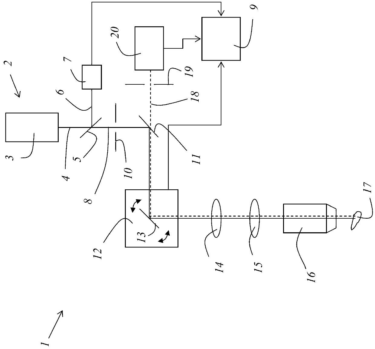
[0057] figure 1 An exemplary embodiment of a scanning microscope comprising a device according to the invention is shown. Scanning microscope 1 is a confocal scanning microscope.

[0058] The scanning microscope 1 has a light source 2 in the form of a pulsed laser 3, which is adapted to generate a rapid sequence of excitation pulses. In particular, a pulsed laser 3 generates a main beam 4 which is incident on a first beam splitter 5 . Here, the main beam 4 is split into a measurement beam 6 and an excitation beam 8 . The measurement beam 6 is directed onto an excitation detector 7 . The excitation detector 7 generates a first analog electrical signal whose amplitude-time curve is proportional to the time curve of the power of the excitation beam 8 . The first analog electrical signal is transmitted to the control device 9 , from which the control device 9 generates a first digital data sequence representing the power-time curve of the excitation beam 8 .

[0059] The exci...


PUM


Abstract

The present invention relates to a method for measuring the lifetime of an excited state in a sample, in particular a fluorescence lifetime, and to an apparatus for carrying out such a method. First, an excitation pulse is generated and a sample region is illuminated with the excitation pulse. Then, a first digital data sequence is generated which is representative of the power-time profile of the excitation pulse, and a first switching instant is determined from the first digital data sequence. Moreover, the detection light emanating from the sample region is detected by a detector, and a second digital data sequence is generated which is representative of the power-time profile of the detection light, and a second switching instant is determined from the second digital data sequence. Finally, the time difference between the first and second switching instants is calculated.

Description

technical field [0001] The present invention relates to a method for measuring the lifetime of an excited state in a sample, in particular, a method for measuring fluorescence lifetime and a device for implementing the method. [0002] The present invention also relates to a device for measuring the lifetime of excited states in a sample, in particular, a device for measuring the fluorescence lifetime, which device includes a light source for generating an excitation pulse to illuminate a sample area with the excitation pulse and for detecting A detector that detects light. Background technique [0003] By analyzing the excited state lifetime of a sample labeled with one or more fluorescent dyes, important information about the properties of the sample can be obtained. Especially when multiple fluorescent dyes are used, information about the analyzed sample region (for example about its composition and environment) can be obtained by utilizing fluorescence lifetime imaging ...

Claims


Application Information

Patent Timeline
Patent Type & Authority Applications(China)
IPC IPC(8): G01N21/64G02B21/00
CPCG01N2201/0697G02B21/0076G01N21/6458G01N21/6408G01N2201/12
Inventor B·威兹高斯盖
Owner LEICA MICROSYSTEMS CMS GMBH
Features
  • R&D
  • Intellectual Property
  • Life Sciences
  • Materials
  • Tech Scout
  • Unparalleled Data Quality
  • Higher Quality Content
  • 60% Fewer Hallucinations
Learn More