Charging method, mobile equipment, charging equipment and charging system

A technology for mobile equipment and charging equipment, applied in the field of communications, can solve the problems of inability to fundamentally reduce the heat loss of mobile equipment, long charging time, and increase in size of mobile equipment.

Active Publication Date: 2013-05-15
HUAWEI DEVICE CO LTD
View PDF6 Cites 18 Cited by
  • Summary
  • Abstract
  • Description
  • Claims
  • Application Information

AI Technical Summary

Problems solved by technology

[0003] Since the current charging circuit is concentrated on the mobile device side, according to the calculation that the highest conversion efficiency of the charging circuit is 93% under ideal conditions, the charging circuit on the mobile device side will generate a heat loss of 0.7W, causing the mobile device to be formed during charging. Heating problem makes users uncomfortable
[0004] In addition, with the rapid development of mobile devices, their battery capacity is getting bigger and bigger, and the charging time is getting shorter and shorter. If you continue to use the previous charging circuit to charge mobile devices, the charging time will be too long. Therefore, the latest USB The standard increases the USB power supply standard, which increases the power supply voltage to 20V and the power supply current to 5A, making it possible to quickly charge mobile devices in a short period of time. However, due to the substantial increase in power supply voltage and power supply current, mobile devices The problem of heating during charging is even more serious. If the latest USB power supply standard is used to provide 20V / 5A current for mobile devices, the charging circuit on the mobile device side will generate a heat loss of 7W. This heat loss is the current mobile device. equipment cannot afford
[0005] In order to solve the current problem of heating of mobile devices during charging, and to adapt the mobile device to the charging mode after increasing the supply voltage and current, cooling measures such as graphite paste or air cooling are adopted on the mobile device side to reduce the charging time of the mobile device. However, this method leads to an increase in the volume of the mobile device, and when the charging current continues to increase, it cannot fundamentally reduce the heat loss of the mobile device, which has caused the limitations of the existing technology

Method used


Image

  • Charging method, mobile equipment, charging equipment and charging system
  • Charging method, mobile equipment, charging equipment and charging system
  • Charging method, mobile equipment, charging equipment and charging system

Examples


Embodiment Construction

[0056] In order to make the object, technical solution and advantages of the present invention clearer, the specific embodiments of the present invention will be further described in detail below in conjunction with the accompanying drawings.

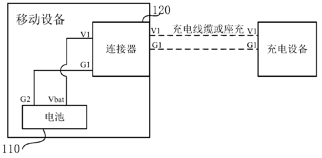
[0057] Below to figure 1 As an example to illustrate the mobile device provided by the embodiment of the present invention, figure 1 It is a schematic structural diagram of a mobile device provided by an embodiment of the present invention.

[0058] exist figure 1 The implementation subject in the illustrated embodiment is a mobile device. exist figure 1 , the mobile device includes the following components: a battery 110 and a connector 120 .

[0059] The connector includes a charge pin V1 and a ground pin G1;

[0060] When the charging pin is connected to the output pin of the charging device through the charging cable or the charger, the charging pin receives the first current signal transmitted by the output pin of the charging...


PUM


Abstract

The invention relates to a charging method, mobile equipment, charging equipment and a charging system. The mobile equipment comprises a battery and a connector. The connector comprises a charging pin and a land pin. When the charging pin is connected with an output pin of the charging equipment through a charging cable or by seat charging, the charging pin receives a first current signal transmitted through the output pin of the charging equipment and transmits the first current signal to a positive pole pin of the battery, and therefore the battery is charged.

Description

technical field [0001] The invention relates to the technical field of communication, and in particular to a charging method, a mobile device, a charging device and a charging system. Background technique [0002] Currently, users usually connect mobile devices (such as mobile phones, tablet computers, etc.) Serial BUS, referred to as: USB) The USB interface is connected to an external device, and can also realize data interaction between the mobile device and the external device or realize charging of the mobile device. [0003] Since the current charging circuit is concentrated on the mobile device side, according to the calculation that the highest conversion efficiency of the charging circuit is 93% under ideal conditions, the charging circuit on the mobile device side will generate a heat loss of 0.7W, causing the mobile device to be formed during charging. The heating problem makes users uncomfortable. [0004] In addition, with the rapid development of mobile device...

Claims


Application Information

Patent Timeline
Patent Type & Authority Applications(China)
IPC IPC(8): H02J7/00H01M10/44H04M1/02
CPCY02E60/12H01M10/44H02J7/00H04M1/02H02J7/00034H02J7/342Y02E60/10H02J7/04H02J7/0045
Inventor 宋刚
Owner HUAWEI DEVICE CO LTD
Why Eureka
Try Eureka