
Speed adjustable magnetic eddy current coupling device

A magnetic eddy current and coupling technology, applied in the field of adjustable speed magnetic eddy current couplings, can solve the problems affecting the speed regulation accuracy of the coupling, low driving efficiency, overheating of pushing parts, etc. Guaranteed stability and reliability, and the effect of preventing vibration

Active Publication Date: 2015-04-15
芜湖铭信电机节能科技有限公司
View PDF2 Cites 0 Cited by
  • Summary
  • Abstract
  • Description
  • Claims
  • Application Information

AI Technical Summary

Problems solved by technology

[0004] At present, the magnetic coupling coupling products with mature technology on the market, such as the related products of Magna Drives in the United States, have been used in the field of motor drive. It is a permanent magnetic coupling variable speed product with high-power models, but due to product Due to the limitations of its own structure and technical solutions, there are still many deficiencies in the technical performance of the product itself that need to be improved, mainly as follows: ①Using permanent magnetic coupling technology, due to the limitations of related working principles, the driving efficiency is low, and the size of the magnetic element and the air gap When conditions such as spacing, rotational speed and slip are determined, the magnetic torque power provided per unit volume is not high, and the heat generation is large, resulting in high-power speed-adjusting products being limited by technical bottlenecks
②The coupling governor itself cannot automatically adjust the air gap spacing, and it needs to be equipped with related devices to realize the adjustment of the air gap spacing. In the process of adjusting the gap, when the pushing part contacts the disk, there will be a " "Dry friction" effect, because the existence of longitudinal force will cause the vibration of the disk and cause overheating and wear of the driving parts
③The mechanical mechanism for adjusting the air gap spacing in the product has inherent technical requirements. For the magnetic turntables that appear in pairs, the gap adjustment mechanism mostly has the characteristics of multiple mechanisms, transmission gaps between mechanisms, and unstable execution reliability. These characteristics affect the Couplings are used in occasions that have high requirements for speed regulation accuracy
[0005] In view of the above technical problems, the present invention proposes a more stable and efficient speed-adjustable magnetic eddy current coupling, and solves the problem of "dry friction" of the thruster during the adjustment of the air gap between the metal disk and the disk, which can be improved and To overcome the shortcomings of the current permanent magnetic coupling coupling products and related technical bottlenecks, improve the application reliability and application occasions of the magnetic eddy current coupling, and provide a feasible core technical solution for the current permanent magnetic coupling speed control equipment market. And it can be applied to industrial production to meet the product needs of permanent magnetic coupling couplings in related fields

Method used


Image

  • Speed adjustable magnetic eddy current coupling device
  • Speed adjustable magnetic eddy current coupling device
  • Speed adjustable magnetic eddy current coupling device

Examples


Embodiment Construction

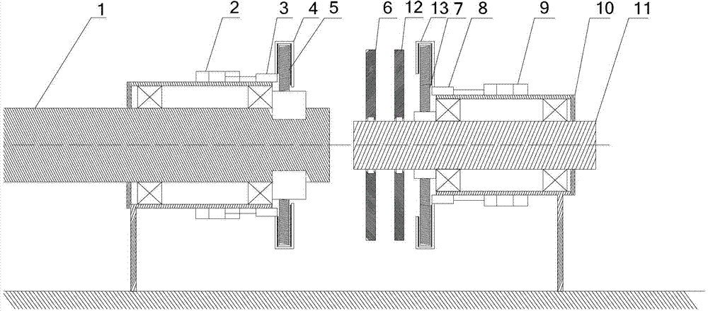
[0018] In order to make the object, technical solution and advantages of the present invention clearer, the present invention will be further described in detail below in conjunction with the accompanying drawings and embodiments. It should be understood that the specific embodiments described here are only used to explain the present invention, not to limit the present invention.

[0019] On the contrary, the invention covers any alternatives, modifications, equivalent methods and schemes within the spirit and scope of the invention as defined by the claims. Further, in order to make the public have a better understanding of the present invention, some specific details are described in detail in the detailed description of the present invention below. The present invention can be fully understood by those skilled in the art without the description of these detailed parts.

[0020] refer to figure 1 Shown is a schematic cross-sectional structure diagram of an adjustable-spee...


PUM


Abstract

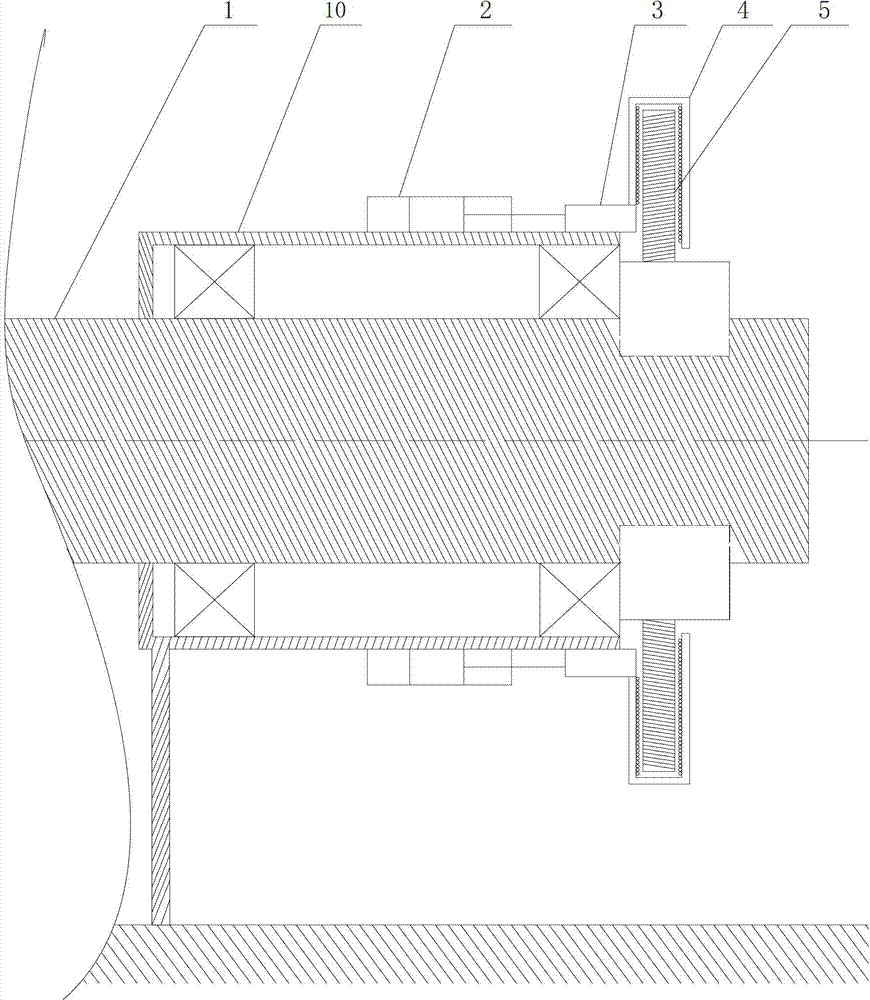
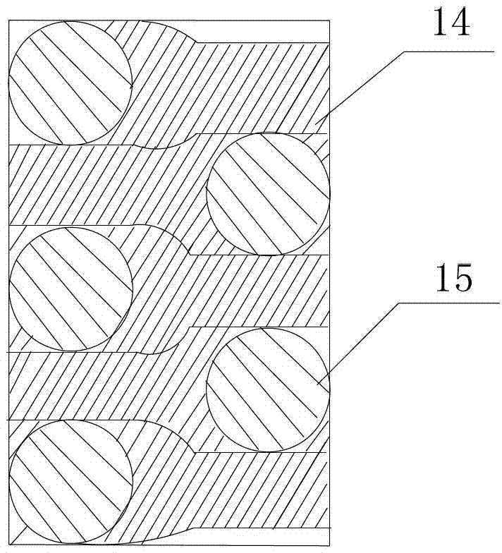
The invention discloses a speed adjustable magnetic eddy current coupling device which comprises a rack, an input shaft, an output shaft, a first metal disc, a second metal disc, a first magnetic disc and a second magnetic disc, wherein a first pushing mechanism regulates the first metal disc to move along the input shaft in a left-and-right mode, a second pushing mechanism regulates the second metal disc to move along the output shaft in a left-and-right mode, the first pushing mechanism and the second pushing mechanism share the same structure and comprise two-way electromagnetic valves, sliding sleeve tubes, outer sleeve tubes and plane ball propellers, the two-way electromagnetic valves are fixed on the rack, the sliding sleeve tubes are fixed at output ends of the two-way electromagnetic valves, the sliding sleeve tubes and the outer sleeve tubes are an integrity, tail ends of the plane ball propellers are respectively connected with the sliding sleeves in a welded mode, an outer shell of each of the plane ball propellers is made of metal plates, and rolling balls capable of rotating in 360 degrees are arranged on the fixed support of the inner side of the metal plates which is opposite to the metal discs. The speed adjustable magnetic eddy current coupling device uses a more reasonable air gap distance regulation mechanism and an executive mechanism, and resolves the problem of 'unlubricated friction'of the propellers in the process of air gap distance regulation of the metal discs and the magnetic discs.

Description

technical field [0001] The invention belongs to the technical field of magnetic eddy current couplings, in particular to a speed-adjustable magnetic eddy current coupling. Background technique [0002] In real life, the drive shaft transmission system connected by a coupling is widely used. Almost industrial occasions and areas involving motor power transmission in life will use the drive shaft transmission technology of the coupling. At present, the couplings used in the mechanical field are mostly mechanical couplings and hydraulic couplings. The mechanical coupling is a rigid connection, and the mechanical force transmits the torque. During the installation process, due to the axial offset error, the load of the supporting original is increased, and the radial offset error will generate a sudden load and cause high-frequency vibration of the equipment, and the rigid connection will generate an impact load at the moment of starting. The speed regulation of the hydraulic ...

Claims


Application Information

Patent Timeline
Patent Type & Authority Patents(China)
IPC IPC(8): H02K51/00
Inventor 杨世锡刘永强甘春标袁海辉池永为王威黄伟迪何俊
Owner 芜湖铭信电机节能科技有限公司
Learn More