
Wheel leg combined type robot

A robot, compound technology, applied in the field of robotics

Inactive Publication Date: 2013-05-22
DALIAN OCEAN UNIV +1
View PDF8 Cites 15 Cited by
  • Summary
  • Abstract
  • Description
  • Claims
  • Application Information

AI Technical Summary

Problems solved by technology

[0003] In order to solve the above-mentioned shortcomings in the prior art, the present invention proposes a vehicle with simple structure, ingenious design, and reasonable layout, which can move quickly under good road conditions and normally travel under poor road conditions. Wheel-legged compound robot

Method used


Image

  • Wheel leg combined type robot
  • Wheel leg combined type robot
  • Wheel leg combined type robot

Examples


Embodiment Construction

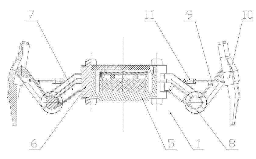
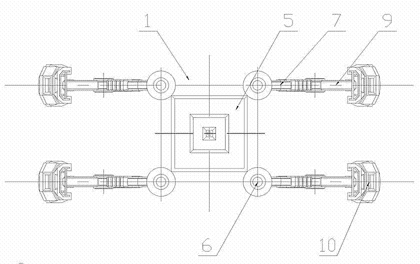
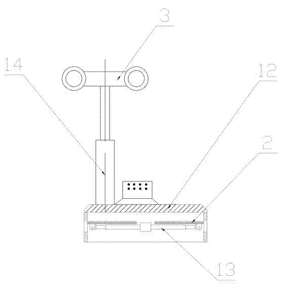
[0017] The specific implementation manner of the present invention will be described below with reference to the accompanying drawings. Such as figure 1 , figure 2 , image 3 , Figure 4 , Figure 5 Shown: a wheel-leg compound robot, which includes a mobile platform 1 capable of driving itself forward, the base of this mobile platform 1 is a shell 5 with a rectangular cross section, and the rectangular cross section of the shell 5 is All four corners are vertically provided with a rotating shaft 6 controlled by a steering motor, on which a thigh 7 is fixedly connected, and the other end of the thigh 7 is provided with a walking wheel 8 controlled by a walking motor. A calf 9 is hinged at the support shaft at the other end of the walking wheel 8, and a walking foot 10 is hinged at the other end of the calf 9. The foot motor is controlled; a hydraulic rod 11 is arranged between the thigh 7 and the calf 9, and the two ends of the hydraulic rod 11 are hinged on the thigh 7 a...


PUM


Abstract

The invention discloses a wheel leg combined type robot structure. When a road condition is good, the wheel leg combined type robot can utilize wheels to drive the wheel leg combined type robot to go forward fast; when the road condition is complex, the wheel leg combined type robot can go forward through walking legs, and the walking legs are convenient and flexible. Energy of the wheel leg combined type robot comes from solar panels, and therefore energy consumption is reduced, and working time is effectively prolonged. So that the wheel leg combined type robot has multiple advantages, is particularly suitable for popularization and application in the field, and has a wide market prospect.

Description

technical field [0001] The invention relates to a robot, in particular to a wheel-leg compound robot that can not only rely on walking wheels but also move on mechanical legs. Background technique [0002] With the development of science and technology, the application of robots has become more and more extensive, and has penetrated into almost all fields. Special-purpose robots can complete tasks such as detection, emergency rescue, and disaster relief in harsh environments. The walking mechanism of traditional robots is often wheeled, tracked or legged. The advantage of the wheel-type walking mechanism is that it moves faster, but it cannot travel or overturns when encountering more complicated road conditions; the advantage of the leg-type walking mechanism is that it can adapt to more complicated road conditions, but the moving speed is slower. At the same time, robots often need to perform sample collection, video collection and other tasks. Therefore need a kind of ...

Claims


Application Information

Patent Timeline
Patent Type & Authority Applications(China)
IPC IPC(8): B62D57/028
Inventor 蔡卫国张文孝高广强张慧峰
Owner DALIAN OCEAN UNIV
Learn More