High pressure conveyance gas recovery method

A high-pressure conveying and gas recovery technology, applied in conveyors, conveying bulk materials, transportation and packaging, etc., can solve problems such as energy waste, and achieve the effect of reducing energy waste, less investment and simple operation

Active Publication Date: 2013-05-22
ANHUI JINMEI ZHONGNENG CHEM IND
View PDF4 Cites 18 Cited by
  • Summary
  • Abstract
  • Description
  • Claims
  • Application Information

AI Technical Summary

Problems solved by technology

[0002] In recent years, with the development of coal gasification technology, pressurized gasification of dry pulverized coal has risen rapidly in China, but high-pressure pulver...

Method used


Image

  • High pressure conveyance gas recovery method

Examples


Embodiment Construction

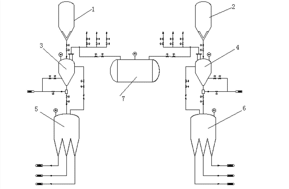
[0020] Referring to the attached drawings, a method for recovering high-pressure conveying gas includes a first storage tank 1, a second storage tank 2, a first lock hopper 3, a second lock hopper 4, a first feed tank 5, and a second feed tank 6 , Gas coupling tank 7, specifically including the following steps:

[0021] a. Storage tank discharge step: the powder in the first storage tank 1 and the second storage tank 2 respectively enters the first lock hopper 3 and the second lock hopper 4 by gravity;

[0022] b. Locking hopper pressurization step: After the first lock hopper 3 and the second lock hopper 4 are filled with powder, they are isolated from the corresponding first storage tank 1, second storage tank 2 and all low-pressure equipment, and communicate with the first lock hopper 3 , The second lock bucket 4 and the gas coupling tank 7 are pressure equalized. After the pressure is balanced, the gas coupling tank 7 is isolated, and the first lock bucket 3 and the second lock...


PUM


Abstract

The invention discloses a high pressure conveyance gas recovery method which comprises a first storage tank, a second storage tank, a first locking hopper, a second locking hopper, a first feeding tank, a second feeding tank and a gas coupling tank. After the first feeding tank (second feeding tank) correspondingly receives a batch of power from the first locking hopper (second locking hopper), the first locking hopper (second locking hopper) is separated from the first feeding tank (second feeding tank). The first locking hopper is opened for equalizing pressure with a communication valve of the gas coupling tank, after pressure is balanced, the second locking hopper is opened for equalizing pressure with the communication valve of the gas coupling tank. When pressure of the first locking hopper, the gas coupling tank and the second locking hopper is balanced, the gas coupling tank is isolated, gases are discharged into a powdered coal storage tank so that a filter is used for discharging pressure of the first locking hopper, and meanwhile, pressure conveyance gases are used for punching the second locking hopper. According to the high pressure conveyance gas recovery method, conveyance gases can be partly recycled, energy dissipation is reduced, and recovery use ratio of conveyance gases is 50% compared with a single system.

Description

Technical field [0001] The invention relates to a method for recovering high-pressure conveying gas. Background technique [0002] In recent years, with the development of coal gasification technology, dry pulverized coal pressurized gasification has rapidly emerged in China, but high-pressure pulverized coal transportation consumes a large amount of N2 / CO2. This part of the transportation gas is completely vented after the transportation is completed, resulting in a lot of waste of energy . The invention can increase the utilization rate of conveying gas, reduce emissions, and reduce energy consumption, and can be widely used in dual-system or multi-system (even) intermittent discharge (conveying) units for high-pressure powder conveying. [0003] The single-system pressurized discharge process in the prior art is as follows: [0004] In one feeding process, the pulverized coal in the normal pressure pulverized coal storage tank enters the pulverized coal lock hopper by gravit...

Claims


Application Information

Patent Timeline
IPC IPC(8): B65G53/34
Inventor 于涛亓为华刘伟柳春王吉林汤心逵李嗣源
Owner ANHUI JINMEI ZHONGNENG CHEM IND
Why Eureka
Try Eureka