
Distributing bucket

A hopper and material shaft technology, which is applied in the processing of building materials, construction, building structure, etc., can solve the problems of inconvenient feeding of the hopper, inconvenient cleaning, low work efficiency, etc., to reduce the cleaning labor intensity, The effect of convenient feeding and manpower saving

Inactive Publication Date: 2013-05-22
江苏中南模板科技有限公司
View PDF5 Cites 3 Cited by
  • Summary
  • Abstract
  • Description
  • Claims
  • Application Information

AI Technical Summary

Problems solved by technology

[0002] The distributing hopper is a common equipment in the existing construction equipment. The feeding of the distributing hopper in the prior art is also inconvenient. The overall cleaning of the equipment requires manpower, which is inconvenient to clean. The stirring shaft in the distributing hopper is a blade parallel to the direction of rotation. , the material cannot be driven to the middle, and the material is easy to adhere to the wall of the distribution hopper. The original feeding shaft is cut from a solid round steel wire. The material cost and labor cost are high, the weight is heavy, the operation is inconvenient, and the work efficiency is low. High, affecting the overall progress of the project

Method used


Image

  • Distributing bucket
  • Distributing bucket
  • Distributing bucket

Examples


Embodiment Construction

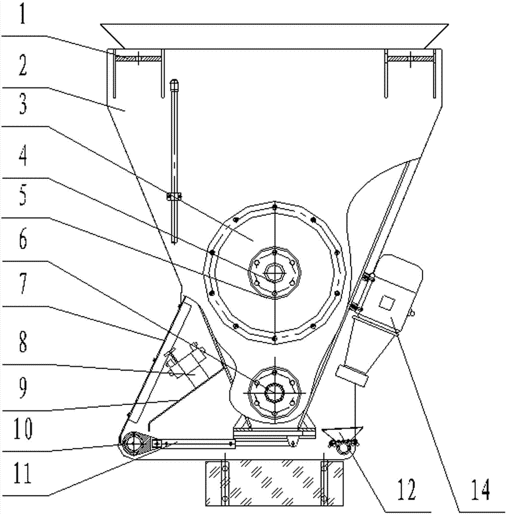
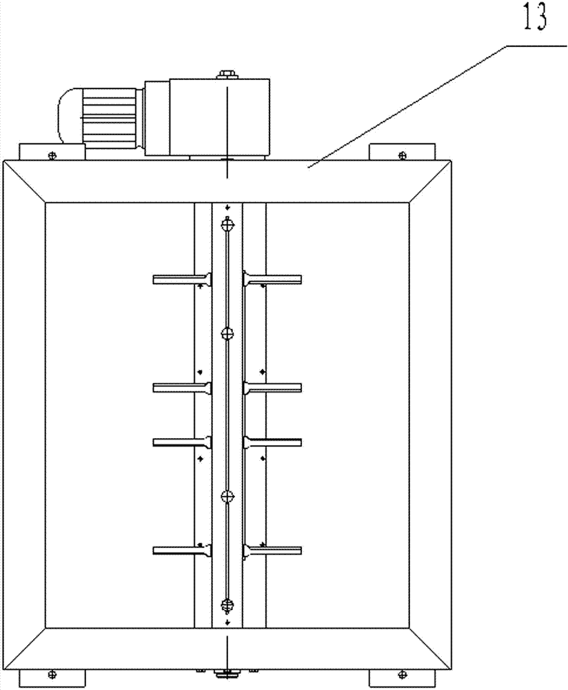
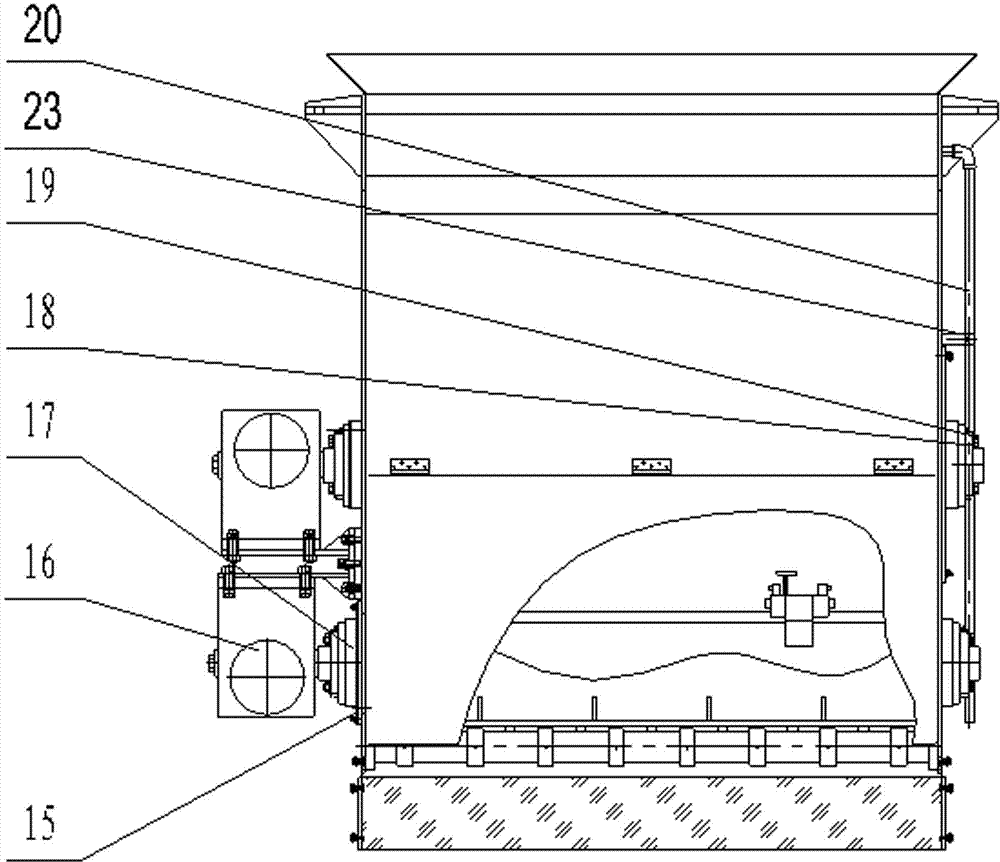
[0021] Such as Figure 1-6 As shown, the distribution hopper of the present invention includes a box body 2, a power motor acceleration and deceleration device 16, a hydraulic pump 14 and a hydraulic solenoid valve 8, and the power motor acceleration and deceleration device 16 is fixed on the motor acceleration and deceleration device mounting seat 13. The hydraulic pump 14 and the hydraulic solenoid valve 8 are respectively arranged on both sides of the bottom of the box body 2, the hydraulic solenoid valve 8 is fixed on the box body 2 through the hydraulic solenoid valve mounting plate 9, and the hydraulic solenoid valve 8 is provided with a cover plate 7. The box body 2 is provided with a stirring shaft 4 and a feeding shaft 6, and the stirring shaft 4 and the feeding shaft 6 are respectively driven by a power motor acceleration and deceleration device 16, and the stirring shaft 4 is connected to the box through a spherical bearing 21. The body 2 is connected, the upper end...


PUM


Abstract

The invention discloses a distributing bucket. The distributing bucket comprises a box body, a motor accelerator-retarder, a hydraulic pump and a hydraulic solenoid valve. A stirring shaft and a discharging shaft are arranged in the box body. The stirring shaft and the discharging shaft are driven by the motor accelerator-retarder respectively. The distributing bucket is characterized in that a hopper type feeding opening is formed in the top of the box body, a weight support is arranged between the hopper type feeding opening and the inner portion of the box body, a box body purge pipe is arranged on one side of the box body, the box body purge pipe and the box body are fixed through a mounting clamp seat, multiple sets of stirring rods are arranged on the stirring shaft, two symmetrical surfaces of each stirring rod forms an angle, an end plate is arranged on a shaft head of the end portion of the feeding discharging opening, the end plate comprises a tubular shaft and vertical plates which are evenly arranged around the tubular shaft, and the end portions of the vertical plates are connected through arc plates. The distributing bucket has the advantages that feeding is convenient, washing labor intensity is reduced, manpower is saved, stirring force to the feeding is increased and side wall adhesion is reduced, materials and labor cost are reduced and the feeding shaft cannot be so heavy.

Description

technical field [0001] The invention relates to the field of construction equipment, in particular to a distribution bucket. Background technique [0002] The distributing hopper is a common equipment in the existing construction equipment. The feeding of the distributing hopper in the prior art is also inconvenient. The overall cleaning of the equipment requires manpower, which is inconvenient to clean. The stirring shaft in the distributing hopper is a blade parallel to the direction of rotation. , the material cannot be driven to the middle, and the material is easy to adhere to the wall of the distribution hopper. The original feeding shaft is cut from a solid round steel wire. The material cost and labor cost are high, the weight is heavy, the operation is inconvenient, and the work efficiency is low. High, affecting the overall progress of the project. [0003] Therefore, there is an urgent need for an improved technology to solve this problem in the prior art. Cont...

Claims


Application Information

Patent Timeline
Patent Type & Authority Applications(China)
IPC IPC(8): E04G21/04
Inventor 黄建国
Owner 江苏中南模板科技有限公司
Learn More