Screw propeller for aerator

An aerator and propeller-type technology, applied in the field of propeller-type aerators, can solve the problems of low stirring force of sewage, shortened reach, and increased fluid loss at the inlet of the propeller, etc., so as to increase the stirring force and reduce the fluid Loss, effect of increasing absolute speed

Active Publication Date: 2013-12-11
HITACHI LTD
View PDF1 Cites 0 Cited by
  • Summary
  • Abstract
  • Description
  • Claims
  • Application Information

AI Technical Summary

Problems solved by technology

[0007] In addition, since the absolute velocity (V) of the water flow at the outlet of the propeller does not increase, the agitation force of the sewage becomes smaller, and the oxygen-dissolved water cannot be sent into the deep and distant part of the aeration tank.
[0008] That is, conventional propellers, including this propeller, are suitable for general water tanks with a water depth of 3 m or less, but are not suitable for application to high water depth tanks exceeding 3 m.
[0009] In addition, in order to increase the absolute velocity (V) of the water flow at the outlet of the propeller, it is necessary to increase the angle (β) formed by the outer edge of the blade and the circumferential direction of the hollow shaft. However, in this case, the conventional In the propeller type aerator, the angle (β) formed by the outer edge of the blade at the inlet of the propeller and the circumferential direction of the hollow shaft must be large.
[0010] However, since the flow at the inlet of the propeller has no swirling component and is a straight flow in the axial direction, if the angle (β) formed by the outer edge of the blade at the inlet of the propeller and the circumferential direction of the hollow shaft increases, there will be The problem of increased fluid loss at the propeller inlet
[0011] And if in the inflow part, the angle (β) formed by the outer edge of the blade of the propeller inlet part and the circumferential direction of the hollow shaft is less than three degrees or more than ten degrees, then there will be a large number of air bubbles around the propeller blade, which will not make the water flow Well Generated Problem Spots
[0012] In addition, since the conventional propeller-type aerator directs the water flow toward the outer peripheral direction of the propeller, that is, because it has a swirl component, as in Figure 11 As shown, the length of the joint between the blade and the hollow shaft is often made larger than the length of the blade in the direction of the winding axis. Therefore, the reach distance of the water flow in the extending direction of the shaft of the propeller is shortened, which is not suitable for application to high water depth tanks. match

Method used


Image

  • Screw propeller for aerator
  • Screw propeller for aerator
  • Screw propeller for aerator

Examples


Embodiment Construction

[0041] Next, embodiments of the propeller type aerator according to the present invention will be described with reference to the drawings.

[0042] Figure 1 to Figure 5 It is an example which shows the propeller type aerator of this invention.

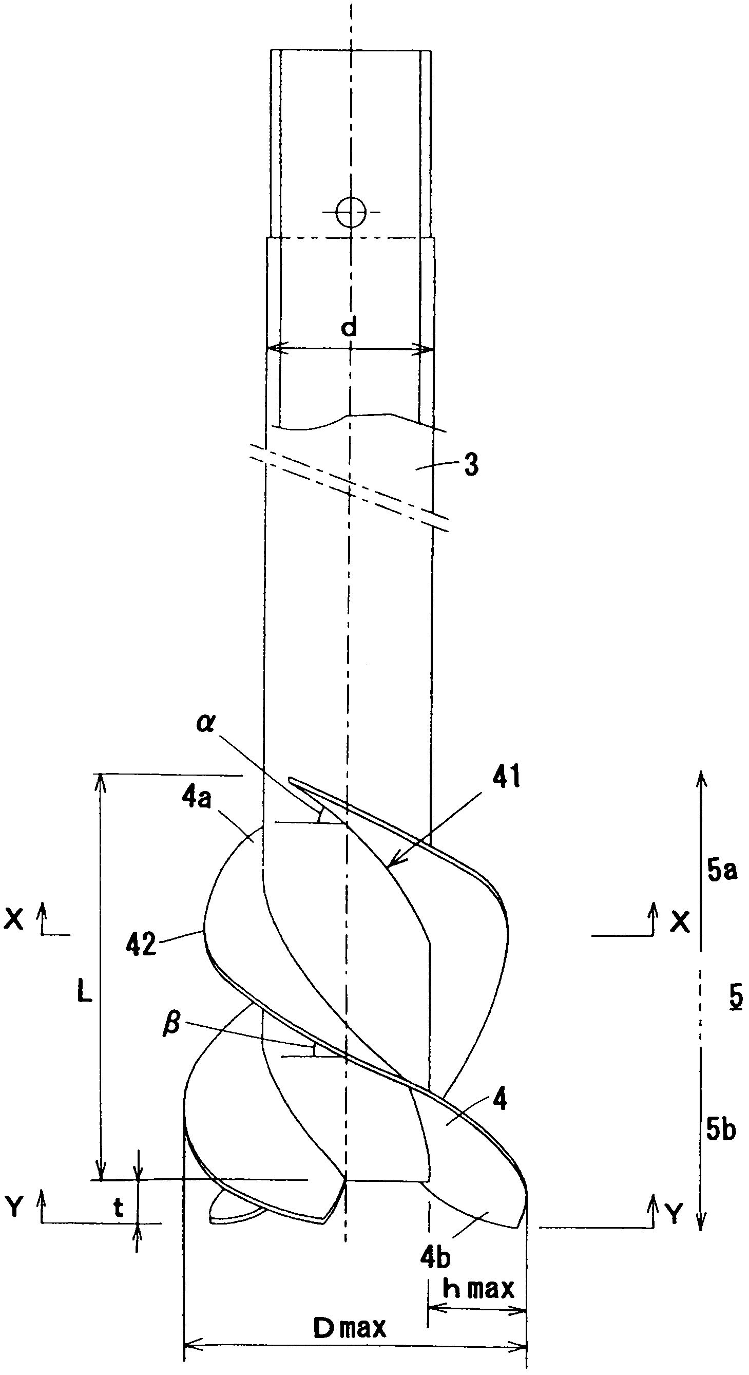
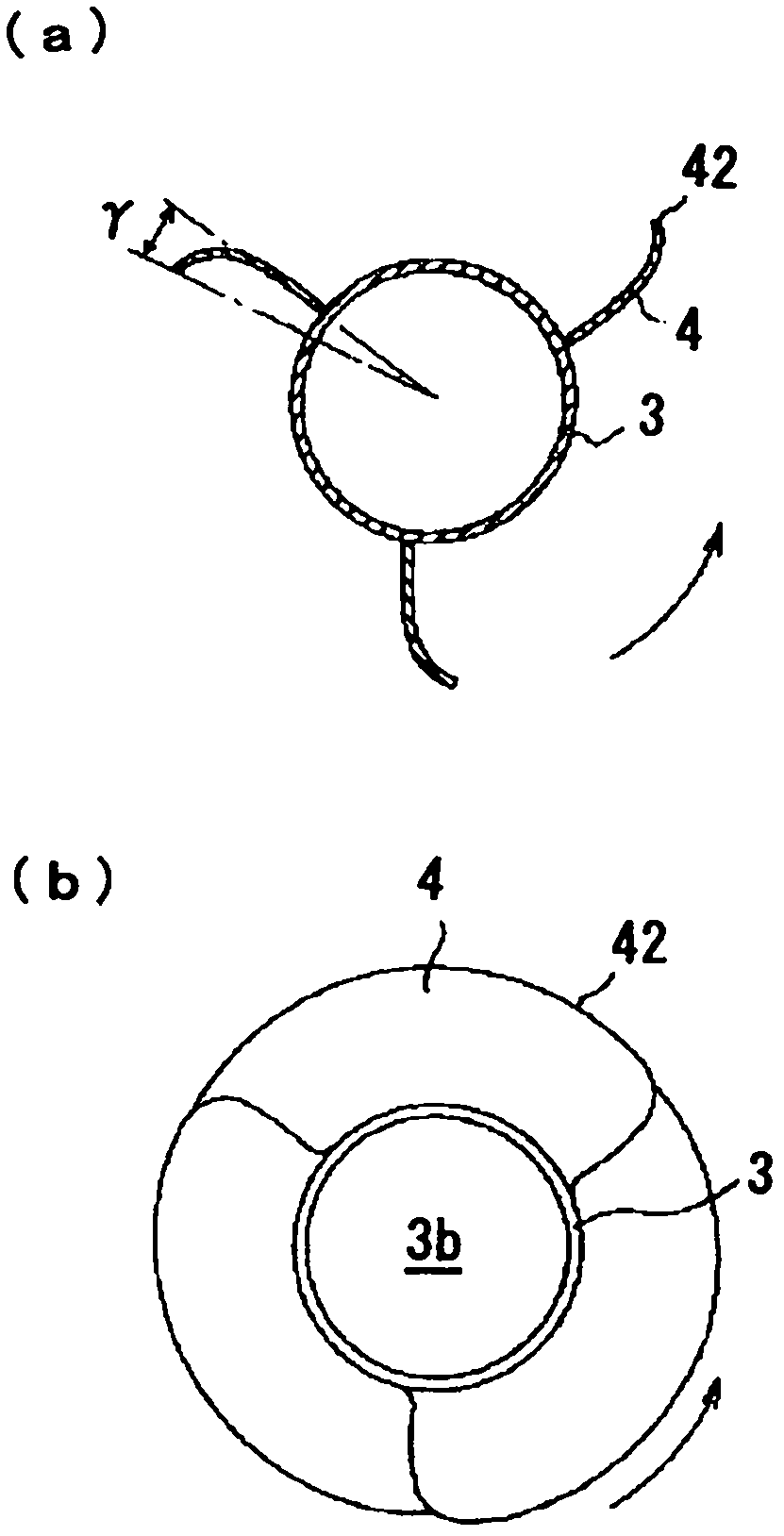
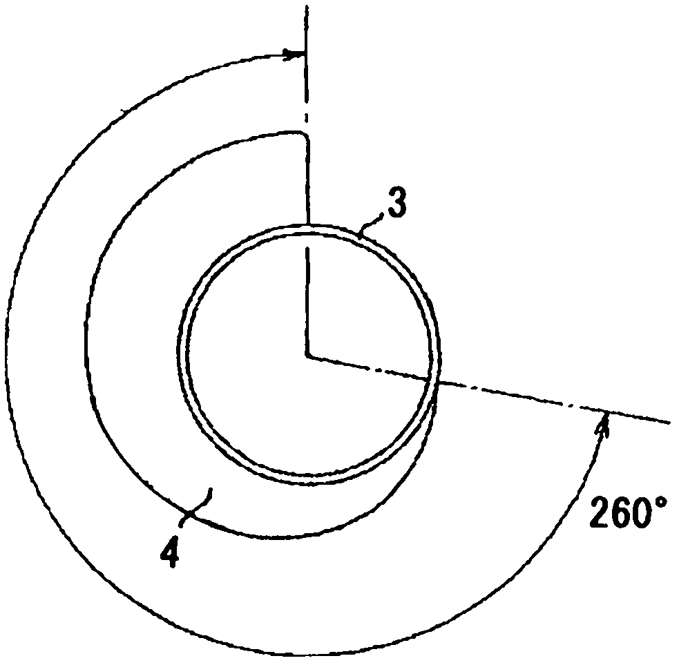
[0043]The propeller-type aerator 1 is arranged in an aeration tank of a wastewater treatment plant, etc., and is rotated by a drive motor 2, and one or more pieces are arranged at the front end of a hollow shaft 3 having an opening 3b at the shaft end to form a spiral. Plate-like blades 4 constitute a propeller 5 .

[0044] The base end of the hollow shaft 3 is penetrated with an air suction hole 3a, and the propeller 5 is rotated in the sewage by the drive motor 2 through the hollow shaft 3, and a negative pressure is generated in the sewage in the front area of ​​the propeller 5. The hole 3 a sucks air, and the sucked air is supplied into the sewage from the opening 3 b formed at the shaft end of the hollow shaft 3 .

[0045] Th...


PUM


Abstract

Provided is a screw propeller for an aerator, featuring excellent aeration performance, simple structure, and easy making, capable of generating necessary bottom flow rate applicable to the groove with high depth of water without specially adding the power of each groove volume. In the invention, the length (L1) of the copula (41) between the blade (4) and the hollow shaft (3) is 1 to 1.5 times of the length of the blade (4) in winding direction; the angle beta, formed by the outer edge (42) of the blade upon the screw propeller outlet portion (5b) and the circumferential direction of the hollow shaft (3), is within the range of 30 to 100 degree; the winding angle (theta) of the blade (4) relative to the hollow shaft (3) is 360 degrees / the number of the blades to 360 degrees; and the ratio (d / Dmax) of the external diameter (d) of the hollow shaft (3) to the maximum diameter (Dmax) of the blades ranges from 0.30 to 0.55.

Description

technical field [0001] The present invention relates to a propeller-type aerator that supplies air (oxygen) to the sewage by stirring sewage to generate negative pressure for aeration. A propeller type aerator with one or more plate-like blades formed in a spiral shape is provided at the front end of the shaft. Background technique [0002] A propeller-type aerator in which a centrifugal blade is combined with a helically formed blade at the front end of a hollow shaft having an opening at the shaft end and, if necessary, is known (for example, See Patent Document 1). [0003] In the case of the self-contained propeller type aerator, if Figure 10 as well as Figure 12 As shown in (a), a propeller structure in which a helical blade 4 is attached to the tip of the propeller shaft, and a centrifugal blade 6 is combined with the tip of the blade 4 as needed. Moreover, in this propeller, as Figure 12 As shown in (b), it is rotated by ventilation, and a negative pressure is ...

Claims


Application Information

Patent Timeline
Patent Type & Authority Patents(China)
IPC IPC(8): C02F7/00
CPCY02W10/10
Inventor 大出浩辅长川秀实水田耕市福本一隆水野昌大
Owner HITACHI LTD
Why Eureka
Try Eureka