
A High Speed ​​Electric Spindle with Composite Bearing

A technology of high-speed electric spindle and composite bearing, which is applied in the direction of metal processing equipment, metal processing machinery parts, manufacturing tools, etc., can solve problems such as heat generation and poor bearing lubrication, reduce heat generation, improve lubrication effect, and reduce wear Effect

Active Publication Date: 2019-11-19
SHANGHAI UNIV
View PDF7 Cites 0 Cited by
  • Summary
  • Abstract
  • Description
  • Claims
  • Application Information

AI Technical Summary

Problems solved by technology

[0007] The purpose of the present invention is to solve the problems of poor bearing lubrication and heat generation in high-speed electric spindles under high-speed and high-pressure working conditions, and provide a high-speed electric spindle with composite bearings

Method used


Image

  • A High Speed ​​Electric Spindle with Composite Bearing
  • A High Speed ​​Electric Spindle with Composite Bearing
  • A High Speed ​​Electric Spindle with Composite Bearing

Examples


Embodiment Construction

[0023] The present invention will be further described below with specific embodiment:

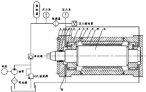
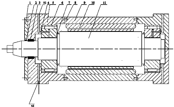
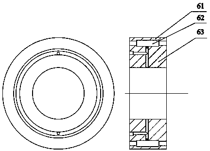
[0024] see Figure 1 to Figure 5 , a high-speed electric spindle with a composite bearing, including a sealing end cover 1, an outer sealing ring 2, an inner sealing ring 3, a first sealing ring 4, a bearing housing 5, a composite bearing 6, a second sealing ring 7, key 8, motorized spindle housing 9, motorized spindle coil 10, rotor 11, the motorized spindle coil 10 is placed inside the motorized spindle housing 9, the rotor 11 is installed in the motorized spindle housing 9, and the composite bearing 6 is installed in In the bearing seat 5, a first sealing ring 4 is arranged between the two. The bearing seat 5 is positioned on both sides of the electric spindle housing 9 through the key 8, and meets the concentricity requirement. There is a For the second sealing ring 7 , an inner sealing ring 3 is arranged between the bearing seat 5 and the rotor 11 , the sealing end cover 1 is fixed t...


PUM


Abstract

The invention relates to a high-speed motorized spindle with a composite bearing. The high-speed motorized spindle with the composite bearing comprises a sealing end cover, an outer sealing ring, an inner sealing ring, a sealing ring made of a special material, a bearing block, the composite bearing, a sealing ring, keys, a motorized spindle shell, a motorized spindle coil and a rotor. The motorized spindle coil is arranged in the motorized spindle shell. The rotor is mounted in the motorized spindle shell. The composite bearing is mounted in the bearing block. The sealing ring made of the special material is arranged between the composite bearing and the bearing block. The bearing block is positioned on the two sides of the motorized spindle shell through the keys. The bearing block and the motorized spindle shell are concentric. The sealing ring is arranged between the composite bearing and the rotor. The inner sealing ring is arranged between the bearing block and the rotor. The sealing end cover is fixed to the bearing block. The outer sealing ring is arranged between the sealing end cover and the rotor. By adopting the high-speed motorized spindle with the composite bearing, the absolute rotating speed of a shaft is greatly increased, and heat generated by lubricating fluid is reduced, so that the lubrication effect of the bearing is improved, and abrasion to the sealing rings is greatly relieved. Double-layer sealing is adopted for a sealing device, and the sealing effect is good.

Description

technical field [0001] The invention relates to the field of precision machining, in particular to a high-speed electric spindle with composite bearings. Background technique [0002] The high-speed electric spindle is the core component of the high-speed machine tool. It combines the machine tool spindle and the variable frequency motor shaft into one, that is, the stator and rotor of the spindle motor are directly installed inside the spindle assembly. It is also called a built-in electric spindle, which is no longer used. Belt or gear transmission pair, so as to realize the zero transmission of the machine tool spindle system. It has the advantages of compact structure, light weight, small inertia, good dynamic characteristics, etc., and improves the dynamic balance of the machine tool, avoids vibration and noise, and has been widely used in ultra-high-speed machine tools. [0003] The electric spindle mainly adopts dynamic and static pressure bearings, angular contact b...

Claims


Application Information

Patent Timeline
Patent Type & Authority Patents(China)
IPC IPC(8): B23B19/02
CPCB23Q1/70
Inventor 张瑾易礼松王小静董健向小青沈杰希聂周
Owner SHANGHAI UNIV
Learn More