
Monophase full-bridge inverter circuit and modulation method thereof

An inverter circuit and single-phase full-bridge technology, applied to electrical components, AC power input to DC power output, output power conversion devices, etc., can solve problems such as common-mode leakage current and common-mode voltage pulsation, and achieve The conduction loss is small, the effect of suppressing the pulsation and improving the efficiency

Inactive Publication Date: 2013-05-22
SHENZHEN HOPEWIND ELECTRIC CO LTD
View PDF3 Cites 5 Cited by
  • Summary
  • Abstract
  • Description
  • Claims
  • Application Information

AI Technical Summary

Problems solved by technology

[0005] One of the technical problems to be solved by the present invention is to provide a single-phase full-bridge inverter circuit to overcome the defects of common-mode voltage ripple and common-mode leakage current in existing single-phase inverter circuits
[0006] The second technical problem to be solved by the present invention is to provide a modulation method for a single-phase full-bridge inverter circuit, which overcomes the common-mode voltage pulsation and common-mode leakage in the existing single-phase inverter circuit modulation method. current defect

Method used


Image

  • Monophase full-bridge inverter circuit and modulation method thereof
  • Monophase full-bridge inverter circuit and modulation method thereof
  • Monophase full-bridge inverter circuit and modulation method thereof

Examples


Embodiment Construction

[0032] The present invention will be further described below in conjunction with the accompanying drawings and embodiments.

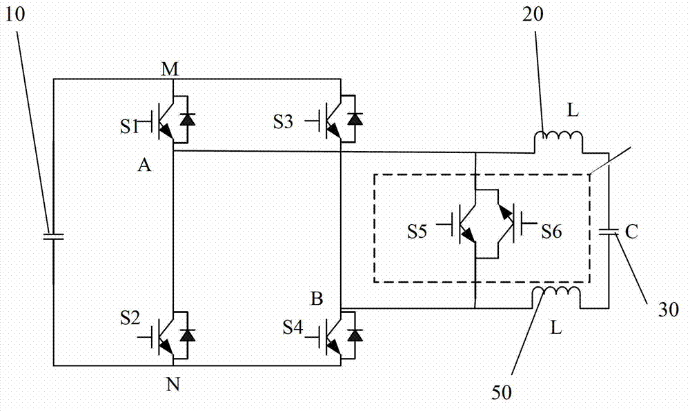
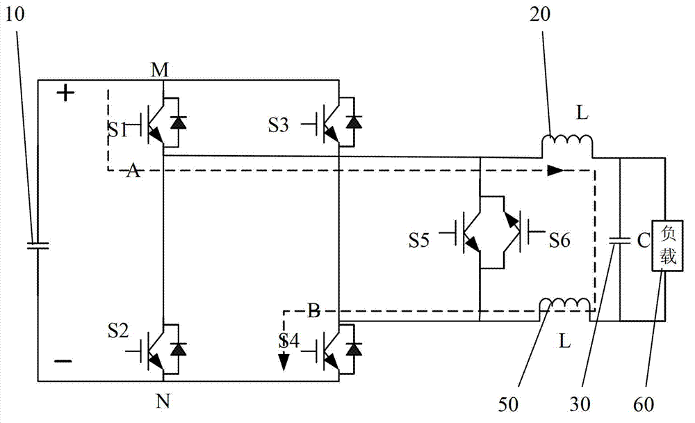
[0033] Such as figure 2 As shown, the single-phase full-bridge inverter circuit of the present invention includes a bus capacitor 10 connected to the DC input terminal, a full-bridge conversion circuit 100, an LCL filter, and anti-impedance IGBTs-S5 and S6. in:

[0034] The LCL filter includes an inductor 20 , a capacitor 30 and an inductor 50 sequentially connected in series (in other embodiments, an LC filter can be used instead of the LCL filter, and the object of the present invention can also be achieved).

[0035] One input terminal M of the full-bridge conversion circuit 100 is connected to the positive pole of the bus capacitor 10 , and the other input terminal N is connected to the negative pole of the bus capacitor 10 . The output terminals A and B of the full-bridge conversion circuit 100 are connected to the LC filter through the inductor...


PUM


Abstract

Disclosed are a monophase full-bridge inverter circuit and a modulation method thereof. The monophase full-bridge inverter circuit comprises a bus capacitor, a full-bridge inverter circuit, a filter circuit, a first reverse-resistance IGBT (insulated gate bipolar transistor) and a second reverse-resistance IGBT. Input ends M and N of the inverter circuit are correspondingly connected with a positive electrode and a negative electrode of the bus capacitor, and output ends A and B of the inverter circuit are connected with the filter circuit. A collector and an emitter of each of the first IGBT and the second IGBT are correspondingly connected with the output end A and the output end B. Each bridge arm of the inverter circuit comprises a switch tube and an inverse-joint diode, an emitter of the first bridge arm and a collector of the second bridge arm are connected with the output end A, and an emitter of the third bridge arm and a collector of the fourth bridge arm are connected with the output end B. A collector of the first bridge arm and a collector of the third bridge arm are connected with the input end M, and an emitter of the second bridge arm and an emitter of the fourth bridge arm are connected with the input end N. Based on the above circuit, the modulation method includes controlling the second IGBT to make in the positive half circle of output voltage and controlling the first IGBT to make in the negative half circle. By the monophase full-bridge inverter circuit, efficiency of inverters is improved, pulse of common mode voltage can be effectively suppressed, and modulation effect is better.

Description

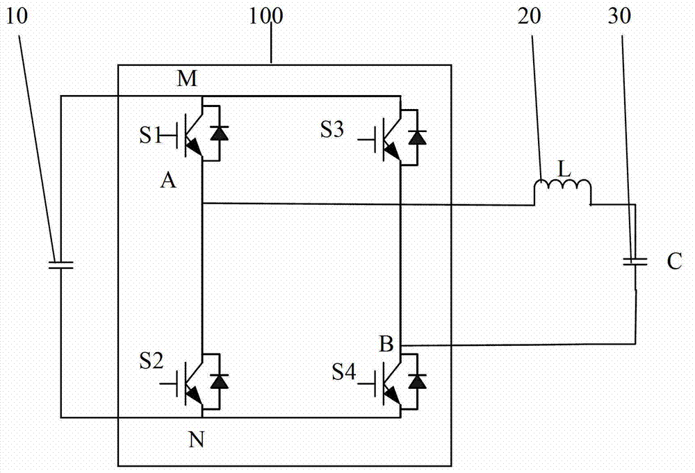
technical field [0001] The invention relates to a single-phase full-bridge inverter circuit, and also relates to a method for modulating the circuit. Background technique [0002] Such as figure 1 As shown, the existing single-phase inverter circuit includes a bus capacitor 10 connected to the DC input terminal, a full-bridge conversion circuit 100 and a filter circuit. The input terminals M and N of the full-bridge conversion circuit 100 are connected to the two ends of the bus capacitor 10, The output terminals A and B are connected to both ends of the filter circuit, M is connected to the positive pole of the bus capacitor 10 , and point N is connected to the negative pole of the bus capacitor 10 . The filter circuit is an LC filter circuit. The LC filter circuit in the full-bridge conversion circuit is composed of an inductor L20 and a capacitor C30. Each bridge arm of the full-bridge conversion circuit 100 includes a switch tube (S1, S2, S3, S4, which can use IGBT or M...

Claims


Application Information

Patent Timeline
Patent Type & Authority Applications(China)
IPC IPC(8): H02M7/5387
Inventor 曾建友陈高曹晓生
Owner SHENZHEN HOPEWIND ELECTRIC CO LTD
Learn More