Heating coil panel

A technology for heating coils and coils, which is applied to coil devices, induction heating, electric heating fuels, etc., can solve the problems of small temperature difference, uneven heat distribution, concentration, etc., and achieve the effects of convenient use, high heating efficiency, and rapid centralized heating.

Inactive Publication Date: 2013-05-22
浙江乐太电器有限公司
View PDF6 Cites 9 Cited by
  • Summary
  • Abstract
  • Description
  • Claims
  • Application Information

AI Technical Summary

Problems solved by technology

[0003] The invention mainly aims at the shortcomings of the heating area of ​​the coil plate being too concentrated and the heat distribution uneven, and invents a heating coil plate, which expands the central area of ​​the winding resistance of the coil and the outer diameter of the coil chassis, so that the heating area is evenly distributed In the annular area in the middle of the coil disk, this area is heated obviously, and the heat is concentrated and heated up quickly. However, due to the expansion of the central area of ​​the winding, the inner diameter of the annular area increases. After calculation, it transmits heat to the outermost periphery and the center point of the bottom of the pot. The speed is similar, so that the heat rising rapidly in the middle annular area spreads evenly to the center point of the pot bottom and the outermost periphery of the pot, so the heat at the bottom of the pot can be more evenly distributed, and the temperature difference of the whole bottom of the pot is relatively small

Method used


Image

  • Heating coil panel
  • Heating coil panel
  • Heating coil panel

Examples


Embodiment 1

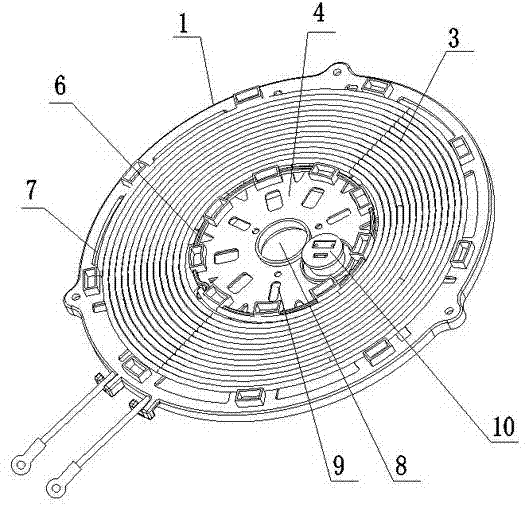
[0033] like figure 1 , 2 As shown in . and 3, a heating coil disk adopts a dense winding method to surround the heating coil 3, including a circular coil chassis 1, and its disk surface is composed of radial support bars, a central circle and an outer ring. The central circle is It is the winding central area 4, and the outer ring is the winding area. In the center of the winding central area 4, there is a circular through hole 8 for installing an external drive motor, and a circle of cooling holes is arranged around the hole 8. 10. There is also a temperature control switch assembly 10 fixed near the edge of the central area 4 of the winding, which consists of a thermistor temperature probe and a thermal fuse that automatically forcibly burns and powers off after reaching a certain limit temperature; if in actual application If required, a heating supplement can be added in the central area of ​​the winding.

[0034] In order to facilitate the passage of the heating coil 3 ...

Embodiment 2

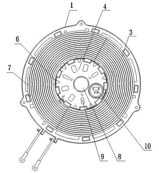
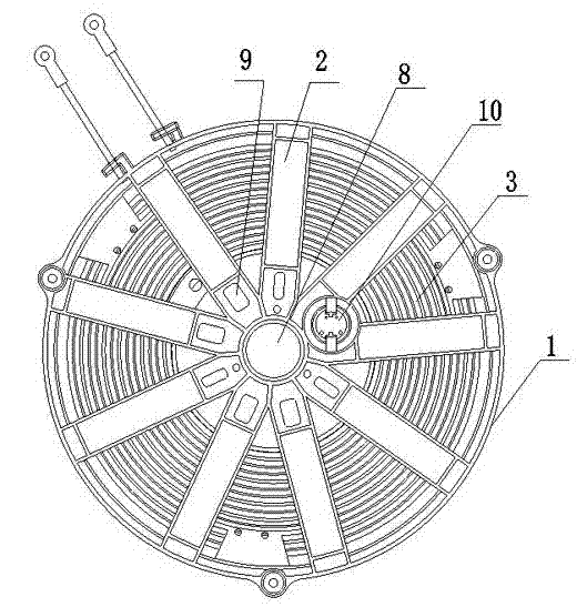
[0038] like Figure 5 , 6 As shown in and 7, a heating coil adopts a loose winding method to surround the heating coil, including a circular coil chassis 1, and its disk surface is composed of radial support bars, a central circle and an outer ring. The central circle is the winding The resistance central area 4, the outer ring is the winding area, wherein, the center of the winding central area 4 has a circular through hole 8 for installing an external drive motor, and a circle of cooling holes 10 is arranged around the hole 8. A temperature control switch assembly 10 is also fixed near the edge of the central area 4 of the winding, which consists of a thermistor temperature probe and a thermal fuse that automatically burns and powers off when it reaches a certain limit temperature; if there is a demand in practical applications , a heating supplementary device can be added in the central area of ​​the winding.

[0039] In order to facilitate the passage of the heating coil...


PUM


Abstract

The invention relates to the electromagnetic induction heating field, in particular to a heating coil panel used for induction cookers. The heating coil panel comprises a coil base panel, and a magnetic stripe, wire slots and heating coils wound in the wire slots which are all arranged on the coil base panel, and further comprises a terminal convenient for coiling of the heating coils, wherein the terminal is composed of an input terminal and an output terminal. The heating coil panel is characterized in that, a winding centre area and a coiling area are arranged on the coil base panel from the centre to the periphery, wherein the diameter of the winding centre area is at least 70mm, a plurality of wire slots are arranged in the coiling area, the wire slots are separated by a plurality of wire slot separation plates, at least one layer of heating coils wound around the wire slots is arranged in the coiling area, more than two layers of heating coils overlapped up and down are arranged in the coiling area, and as the number of layers of the coils increases, distances from the heating coils to the center of the coil base panel gradually increase, and therefore the heating coils are in a ladder shape with the width gradually increasing from top to down. The heating coil panel is large in the outer ring, large in heating area coverage, rapid and uniform in heat spread, and high in heating efficiency.

Description

technical field [0001] The invention relates to the field of electromagnetic induction heating, in particular to a heating coil disk used in an electromagnetic oven. Background technique [0002] Coil disks generate heat and provide heat for induction cookers, cooking pots, etc. The existing coil disks have been making efforts to improve energy efficiency, and have achieved remarkable results. The area is often concentrated in a very small circular area in the center of the coil disk. In addition, the heat dissipation rate from the center of the pot body to the edge is too slow, resulting in heat concentration and local high temperature in the center. Therefore, the energy efficiency is indeed improved, but the heating is only concentrated in the center of the bottom pot. One point, the food in the pot is not evenly heated, and it is easy to burn, so it is naturally impossible to make delicious food. Contents of the invention [0003] The invention mainly aims at the shor...

Claims


Application Information

Patent Timeline
Patent Type & Authority Applications(China)
IPC IPC(8): H05B6/40F24C7/06
Inventor 应高峰应高波陆建峰胡振宇
Owner 浙江乐太电器有限公司
Why Eureka
Try Eureka