Energy-conservation machine tool main shaft drive mechanism and matched lanthanon permanent magnet motor

A rare-earth permanent magnet motor and machine tool spindle technology, which is applied in the direction of magnetic circuit rotating parts, magnetic circuit shape/style/structure, etc., can solve problems such as large reverse starting current, easily damaged components, and energy-consuming system impact

Inactive Publication Date: 2013-05-29
宁德市优力维特电梯配件有限公司
View PDF8 Cites 4 Cited by
  • Summary
  • Abstract
  • Description
  • Claims
  • Application Information

AI Technical Summary

Problems solved by technology

[0004] During the working process of the machine tool, the forward, reverse and dry running are repeated. The starting current of the three-phase asynchronous motor is large, generally 2 ...

Method used


Image

  • Energy-conservation machine tool main shaft drive mechanism and matched lanthanon permanent magnet motor
  • Energy-conservation machine tool main shaft drive mechanism and matched lanthanon permanent magnet motor
  • Energy-conservation machine tool main shaft drive mechanism and matched lanthanon permanent magnet motor

Examples


Embodiment Construction

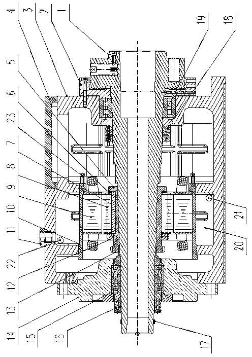
[0022] Novel machine tool spindle drive mechanism of the present invention, as figure 1 As shown, it includes a spindle box 3 and a permanent magnet motor built in the spindle box 3 and a machine tool spindle 1. The permanent magnet motor includes a motor stator 9 and a motor rotor 8 for driving the machine tool spindle 1 to run. The permanent magnet motor The motor casing 10 is supported and connected by two supporting rings arranged on the inner wall of the spindle box 3, so as to form a sealed cooling fluid circulation between the outer wall of the motor casing 10, the inner wall of the spindle box 3 and the two supporting rings Cavity 20.

[0023] The above-mentioned headstock 3 is respectively provided with a cooling fluid inlet 21 and a cooling fluid outlet 22 connected with the flow cavity 20 on the side wall between the two support rings, so as to inject and To discharge the cooling fluid, a cooling fluid temperature measuring probe fixing base 11 is provided on the s...


PUM


Abstract

The invention relates to the machine tool manufacturing technical field, in particular to an energy-conservation machine tool main shaft drive mechanism and a matched lanthanon permanent magnet motor. The energy-conservation machine tool main shaft drive mechanism comprises a main shaft box and a permanent magnet motor and a machine stool motor which are installed in the main shaft box. The permanent magnet motor comprises a motor stator and a motor rotor used for driving the machine stool main shaft to operate. A motor shell of the permanent magnet motor is supported and connected by two support ring bodies arranged in the inner side wall of the main shaft box, a sealed cooling fluid circulating cavity channel is formed between the outer side wall of the motor shell, the inner side wall of the main shaft box and the two support ring bodies. The energy-conservation machine tool main shaft drive mechanism is compact in structure, reasonable in distribution, small in construction element, easy to manufacture, dismount and maintain, and good in use effect.

Description

technical field [0001] The invention relates to the technical field of machine tool manufacturing, in particular to an energy-saving machine tool spindle drive mechanism and its matching rare earth permanent magnet motor. Background technique [0002] Most of the existing ordinary machine tools in our country use three-phase asynchronous motors to drive through the first-stage belt, and then the head box performs two or three gear shifts to realize the transmission work, but this structure has the following shortcomings: [0003] The matching three-phase asynchronous motor generally has a speed of 1400 rpm or 2800 rpm, while the applicable working speed of ordinary machine tools is generally between 50 and 2500 rpm. Therefore, belts and gears must be used for multi-pole speed change. This transmission method has obvious mechanical loss. Generally, the mechanical loss of the first-stage belt transmission is 4-7%, and the mechanical loss of the first-stage gear transmission is...

Claims


Application Information

Patent Timeline
IPC IPC(8): B23B19/00B23B19/02H02K1/27
Inventor 郭自刚
Owner 宁德市优力维特电梯配件有限公司
Why Eureka
Try Eureka