Nail-free fall plate type roadblock preventing automobile from rushing across

An anti-collision and drop-off technology, which is applied to roads, roads, traffic restrictions, etc., can solve the problems of inability to control or restrict traffic according to needs, poor anti-collision strength, and large space occupation, achieving small space occupation, assembly and disassembly, etc. Convenience and simple structure

Inactive Publication Date: 2014-11-26
XIAMEN YUSHENGJIE MECHANICAL & ELECTRICAL TECH
View PDF12 Cites 1 Cited by
  • Summary
  • Abstract
  • Description
  • Claims
  • Application Information

AI Technical Summary

Problems solved by technology

There are following deficiencies in this kind of anti-shock barrier: 1. the thorns are fixed on the rotating shaft, and the thorns can move relative to the base, and the impact resistance is poor. When impacting, the thorns, the rotating shaft and the motor are all easily damaged; 2. the whole The structure is complex and takes up a lot of space; 3. There are long holes, which bring inconvenience to the driving of cars or personnel or other vehicles
This kind of anti-shock roadblock has the following shortcomings: 1. The function is single, and it can only be controlled by gravity whether to pass or restrict traffic, and cannot control traffic or restrict traffic according to demand; 2. The whole structure is complex and takes up a lot of space; 3. There are long strips Holes, causing inconvenience to the driving of cars or people or other vehicles

Method used


Image

  • Nail-free fall plate type roadblock preventing automobile from rushing across
  • Nail-free fall plate type roadblock preventing automobile from rushing across
  • Nail-free fall plate type roadblock preventing automobile from rushing across

Examples


Embodiment Construction

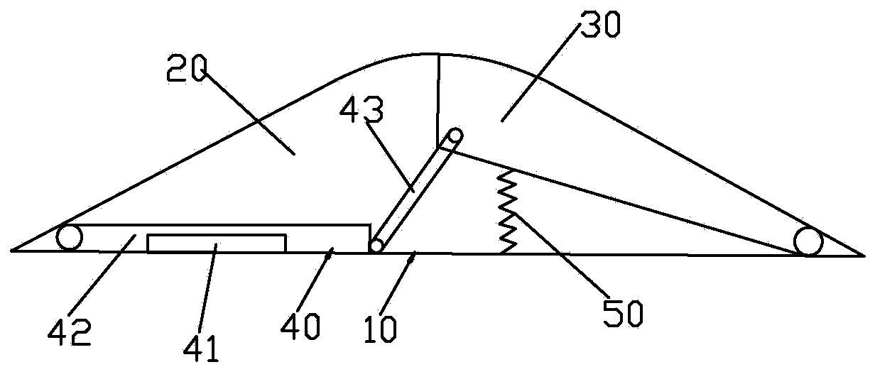
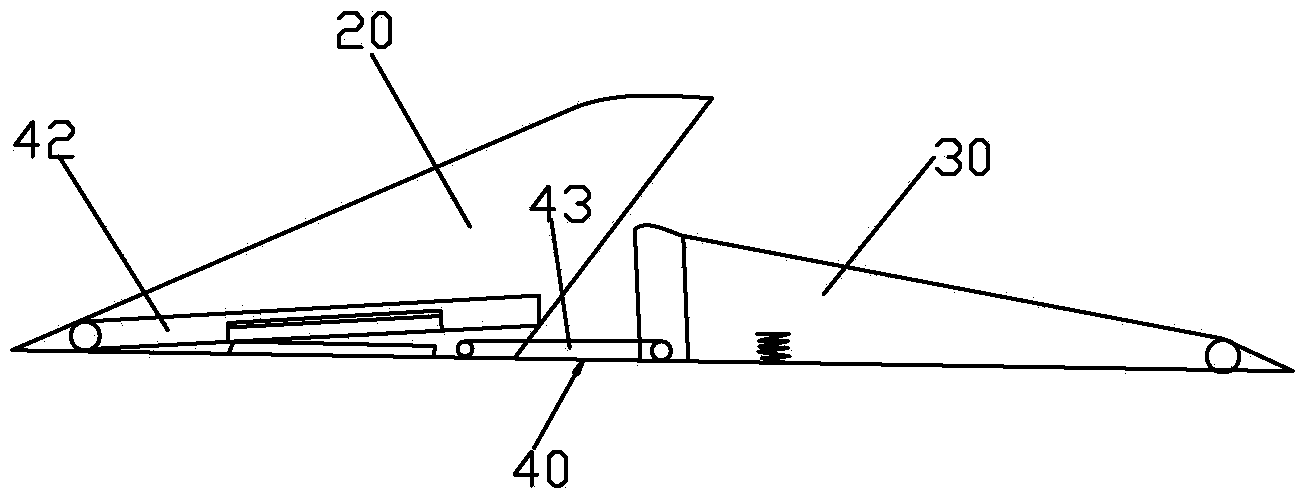
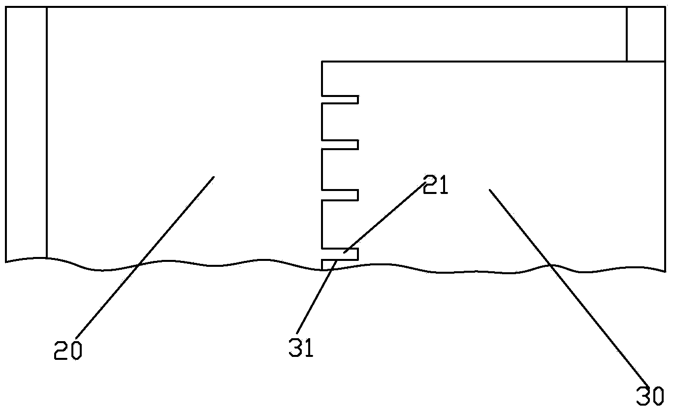
[0024] Please check figure 1 , figure 2 and image 3 , a nail-free plate-type anti-shock barrier, including a base 10, a solid seat 20, a movable seat 30, a driving mechanism 40 and an elastic body 50.

[0025] The base 10 is, for example, a bottom plate. If required, if it is directly constructed on the ground, the ground is considered as the base. The fixed seat 20 and the movable seat 30 are connected to the base 10 in a front-rear arrangement, the front-rear relationship refers to the front-rear relationship along the vehicle traveling direction, which can be formed as an integral structure, which is convenient for assembly and disassembly, safe and reliable. Moreover, the top surface of the movable seat 30 and the top surface of the fixed seat 30 that are positioned at the allowable position cooperate to form an arch, so the existing road surface need not be damaged, and the device can be directly arranged on the road surface. Moreover, its shape is similar to that of ...


PUM


Abstract

The invention discloses a nail-free fall plate type roadblock preventing an automobile from rushing across. The roadblock comprises a base, a fixed seat, a movable seat and a drive mechanism. The fixed seat is fixedly connected to the base, the movable seat is connected to the base in a rotating mode, and the drive mechanism is in transmission connection with the movable seat so that the movable seat can rotate between a traffic forbidden position and a traffic allowable position. The side, facing the movable seat, of the fixed seat is provided with protrusions. The side, facing the fixed seat, of the movable seat is provided with grooves. The part, located at the traffic forbidden position, of the movable seat is staggered with the protrusions in the vertical direction to expose the protrusions so that the protrusions can penetrate into tires of the automobile which rushes across; the part, located at the traffic allowable position, of the movable seat is aligned with the protrusions, and the protrusions are matched with the grooves to prevent the protrusions from acting on the automobile. The roadblock has the advantages that the roadblock is free of sharp tooth tips, has an automatic reset function and will not cause any danger to staff; electromagnetic drive is adopted, and the roadblock is simple in structure and low in manufacturing cost; the roadblock can be set to be opened or closed constantly and is capable of preventing the automobile to rush across and reliable; manual control and remote control can be adopted, and therefore man-made sabotage can be prevented; besides, the roadblock is high in adaptability, capable of resisting rainwater and easy and convenient to assemble, disassemble and maintain.

Description

technical field [0001] The invention relates to a nail-free plate type anti-shock barrier. Background technique [0002] The existing anti-shock barriers mainly include the following categories: [0003] The first kind, anti-shock closing roadblock, its basic structure is: comprise two bases, a rotating shaft, a flat plate and motor. The rotating shaft is rotatably connected to the two bases and can rotate between the limit position and the allowable position, and a plurality of thorns are fixed on the rotating shaft. The plate is provided with a plurality of elongated holes, and the spurs correspond to the elongated holes. When at the allowed position, the thorns did not stretch out the elongated hole, and when at the limit position, the thorns stretched out the elongated hole. Such anti-shock barriers are for example CN00105200.4, 201210427993.1, CN201310369074.8, CN98215043.1, CN200520139575.8, CN200620134759.X published and announced in the Chinese patent database. T...

Claims


Application Information

Patent Timeline
Patent Type & Authority Applications(China)
IPC IPC(8): E01F13/04
Inventor 刘玉恩赖雅琳
Owner XIAMEN YUSHENGJIE MECHANICAL & ELECTRICAL TECH
Why Eureka
Try Eureka