
Material distribution device for magnesite electric smelting furnace

A technology of electric fused magnesium furnace and material distributing device, which is applied in the direction of furnace materials, furnaces, crucible furnaces, etc., can solve the problems of great safety hazards, threats to the health of operators, and difficulty in ensuring the uniformity of material distribution, so as to reduce labor intensity and install Easy dismantling and maintenance, and the effect of avoiding injury

Pending Publication Date: 2019-02-19
UNIV OF SCI & TECH LIAONING +1
View PDF0 Cites 0 Cited by
  • Summary
  • Abstract
  • Description
  • Claims
  • Application Information

AI Technical Summary

Problems solved by technology

In the past, when the company was producing, the fused magnesium furnace used the form of two people and four points of distribution. The personnel had to swing the distribution funnel to distribute the material into the furnace at any time. It was difficult to ensure the uniformity of the distribution; Potential safety hazards are relatively large; in addition, the working environment of operators is particularly harsh, such as dust pollution caused by high-temperature radiation in the furnace and mineral powder, which seriously threaten the health of operators

Method used


Image

  • Material distribution device for magnesite electric smelting furnace
  • Material distribution device for magnesite electric smelting furnace

Examples


Embodiment Construction

[0024] The specific embodiment of the present invention will be further described below in conjunction with accompanying drawing:

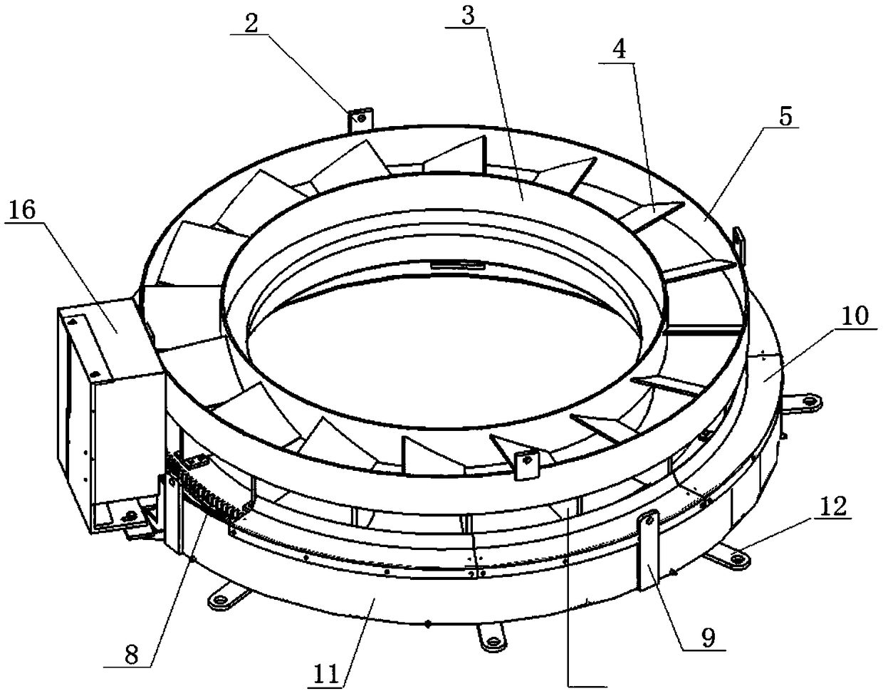
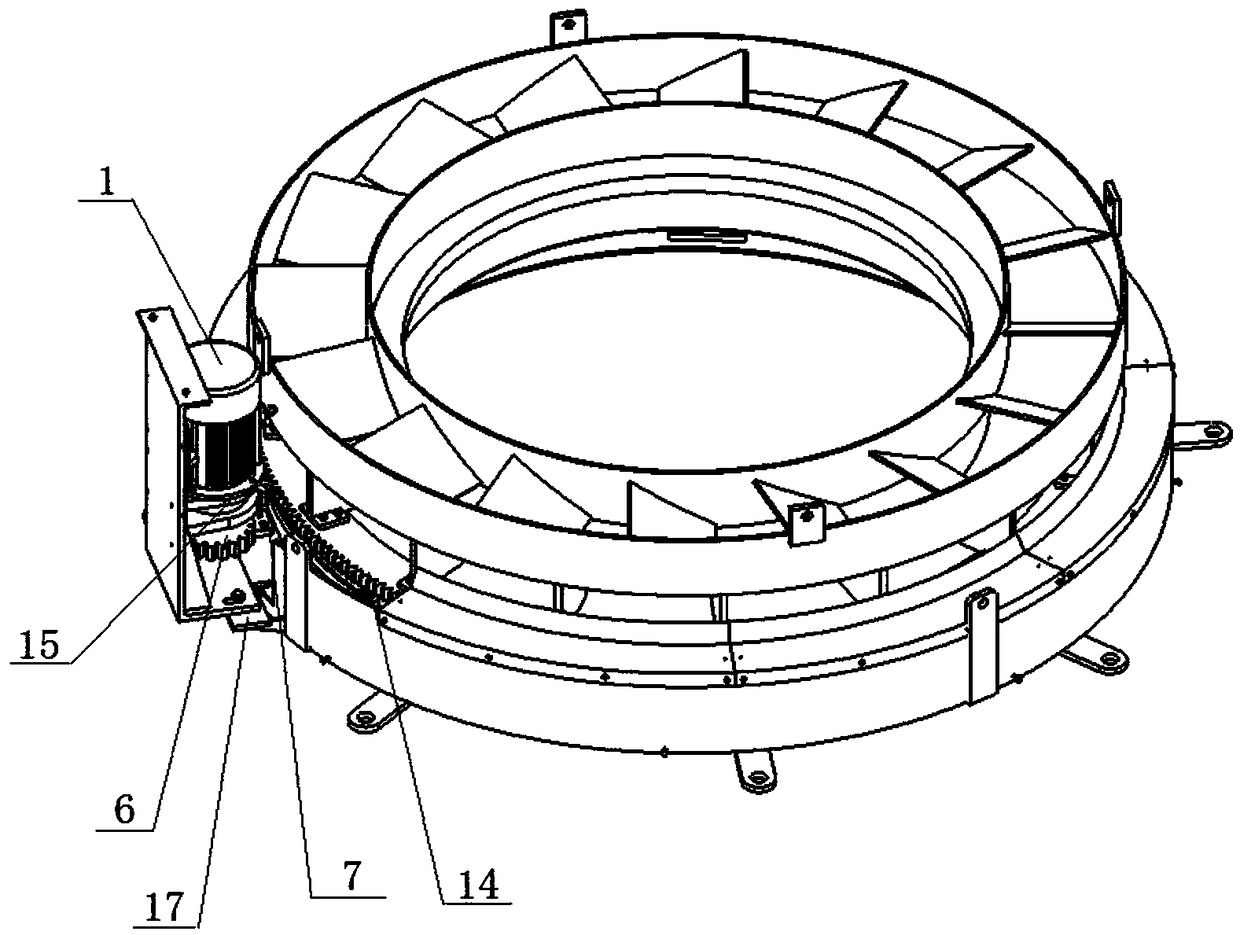
[0025] like figure 1 , figure 2 As shown, a material distribution device for an electric fused magnesium furnace according to the present invention is arranged above the furnace mouth of the electric fused magnesium furnace; it includes a fixed assembly, a rotating assembly, a motor 1 and a transmission device; the fixed assembly consists of a bottom ring 11 and cover body 10, wherein the bottom ring 11 is fixedly connected with the furnace mouth of the fused magnesium furnace; A plurality of support wheels 14 are supported on the bottom ring 11, the outer ring 5 is fixed on the inner side of the bottom ring 11, and the outer ring 5 is connected with the inner ring 3 through a plurality of fan blades 4; the motor 1 drives the ring gear 8 on the bottom ring through a transmission device. 11, the rotating distribution mechanism consisting of oute...


PUM


Abstract

The invention relates to a material distribution device for a magnesite electric smelting furnace. The material distribution device is arranged above a furnace mouth of the magnesite electric smeltingfurnace. The material distribution device comprises a fixing assembly, a rotating assembly, a motor and a transmission device. The fixing assembly is composed of a bottom ring and a cover body, wherein the bottom ring is fixedly connected with the furnace mouth of the magnesite electric smelting furnace. The rotating assembly is composed of a gear ring, an inner ring, an outer ring and fan blades. The bottom of the gear ring is supported on the bottom ring through a plurality of supporting wheels. The outer ring is fixed to the inner side of the bottom ring. The outer ring is connected with the inner ring through the fan blades. The motor drives the gear ring to rotate on the bottom ring through the transmission device. A rotary material distribution mechanism composed of the outer ring,the inner ring and the fan blades rotates along with the gear ring. The top of the bottom ring on the outer side of the outer ring is enclosed through the cover body. The material distribution deviceprovided by the invention is compact in structure, uniform in material distribution, capable of realizing mineral powder and mineral discharging in different areas, high in material distribution efficiency and high in protective property and sealing performance. The material distribution device can implement full-automatic material distribution after being in joint control with a discharging gate.

Description

technical field [0001] The invention relates to the technical field of furnace top material distribution, in particular to a material distribution device for an electric fused magnesium furnace. Background technique [0002] Since entering the 21st century, with the rapid development of society and economy, the requirements of enterprises for work efficiency and employees for work environment are also constantly improving. In the past, when the company was producing, the fused magnesium furnace used the form of two people and four points of distribution. The personnel had to swing the distribution funnel to distribute the material into the furnace at any time. It was difficult to ensure the uniformity of the distribution; Potential safety hazards are relatively large; in addition, the working environment of operators is particularly harsh, such as high-temperature radiation in the furnace, dust pollution caused by mineral powder, etc., which seriously threaten the health of ...

Claims


Application Information

Patent Timeline
IPC IPC(8): F27B14/16
CPCF27B14/0806F27M2003/13F27B2014/0812
Inventor 周建洪尚德虹焦安源陈福龙秦海滨
Owner UNIV OF SCI & TECH LIAONING
Learn More