A method for preparing a radial permanent magnet ring and its manufacturing device

A technology for preparing a device and a permanent magnet ring, which is applied in the manufacture of inductors/transformers/magnets, permanent magnets, electrical components, etc., can solve the problem of poor uniformity of orientation degree of radial permanent magnet rings, reduction of orientation magnetic field strength, uneven orientation degree, etc. problems, to achieve the effect of improving the uniformity of radial orientation, improving uniformity, and improving the yield of molding

Active Publication Date: 2016-01-06
ORIENT MAGNET TECH OMT
View PDF9 Cites 0 Cited by
  • Summary
  • Abstract
  • Description
  • Claims
  • Application Information

AI Technical Summary

Problems solved by technology

There are four main methods of preparing radial permanent magnet rings by sintering process: the method of extruding magnetic field orientation, in which the upper and lower magnetic pole heads of the same sex are squeezed into the radial ring mold cavity during the pressing process, and a radiation magnetic field is formed through magnetic conduction , the radial permanent magnet ring prepared by this method has poor orientation uniformity in the height direction. In addition, when a magnetic ring with a higher height or a smaller inner diameter is prepared, the intensity of the orientation magnetic field will be greatly reduced; the segmental orientation method , this method orients the ring in segments, but it will lead to uneven orientation at the segment, resulting in uneven magnetic properties of the final magnetic ring, and even cracking due to stress concentration; forming orientation method: this method is used during the pressing process There is a relative rotational movement between the magnetic powder and the orientation magnetic field, which better solves the inhomogeneity of segmental orientation, but because the pressing is also carried out synchronously during the orientation process, this method also has the problem of uneven orientation; rotation Magnetic field orientation: This method uses the alternating current of the electromagnet to generate a rotating magnetic field to orient the magnetic ring, but the magnet still has uneven orientation along the circumferential direction

Method used


Image

  • A method for preparing a radial permanent magnet ring and its manufacturing device

Examples


Embodiment Construction

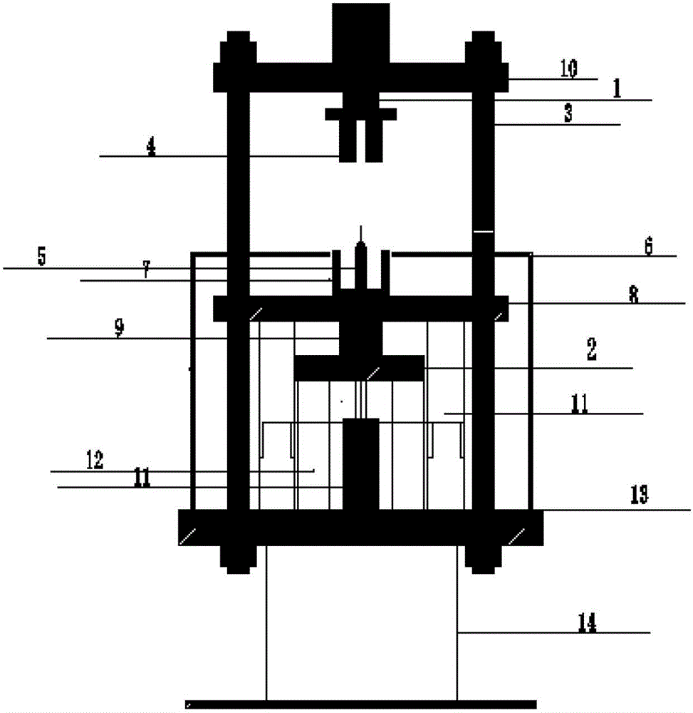
[0018] The present invention will now be described in further detail in conjunction with the accompanying drawings and preferred embodiments. These drawings are all simplified schematic diagrams, which only illustrate the basic structure of the present invention in a schematic manner, so they only show the configurations related to the present invention.

[0019] Such as figure 1 The radial permanent magnetic ring preparation device shown: the outer mold cavity is a detachable circular cylinder, which is fixed on the movable plate, and the outer mold cavity is fixed on the movable plate made of non-magnetic material, which can be moved up and down by the movable plate And drive the movement of the outer mold cavity; the upper punch of the press is a detachable circular ring, the lower punch is fixed on the non-magnetic fixed plate, and its position remains fixed during the pressing process; the center mandrel is held by the magnetic It is made of high-quality material and act...


PUM

PropertyMeasurementUnit
thicknessaaaaaaaaaa

Abstract

The invention provides a method for manufacturing a radial permanent magnetic ring and a manufacturing device of the method. In the orienting and pressing process of permanent magnetic powder placed in an annular die cavity, the magnetic powder with a certain thickness is always located in a radial magnetic field and is oriented, the radial magnetic field conducts reciprocating scanning motion on the magnetic powder in the axial direction, and therefore the magnetic powder at different height positions is enabled to be sequentially located in the radial magnetic field, and finally all the magnetic powder is oriented. After the pressing process is over, the radial permanent magnetic ring with the magnetic powder which is sufficiently and evenly oriented in the radial direction is obtained.

Description

technical field [0001] The invention relates to a method for preparing a radial sintered permanent magnet ring and a manufacturing device thereof, in particular to a method and a manufacturing device thereof capable of realizing the radial orientation of a ring-shaped magnet with any thickness and height. Background technique [0002] The orientation mentioned in the magnet means that under the action of the magnetic field, the direction of the easy magnetization axis in the crystal of the magnetic powder turns to the direction consistent with the direction of the magnetic field, so that the magnetic powder forms an orderly arrangement in a certain direction. At present, there are mainly four orientation modes of ring magnets in this field, namely axial orientation, radial orientation, radial orientation and radial multi-pole orientation. Among them, both axially oriented and radially oriented permanent magnet rings have been able to be mass-produced, and radially multi-leve...

Claims


Application Information

Patent Timeline
Patent Type & Authority Patents(China)
IPC IPC(8): H01F41/02H01F7/02B22F3/03B22F3/02
Inventor 王军文董生智廖超马世光
Owner ORIENT MAGNET TECH OMT
Why Eureka
Try Eureka