A preparation device for radially oriented permanent magnet rings

A technology for preparing devices and permanent magnetic rings, which is applied in the fields of permanent magnets, inductors/transformers/magnets, and electrical components. Orientation uniformity, improvement of uniformity, and improvement of pass rate

Active Publication Date: 2016-06-01
ORIENT MAGNET TECH OMT
View PDF13 Cites 0 Cited by
  • Summary
  • Abstract
  • Description
  • Claims
  • Application Information

AI Technical Summary

Problems solved by technology

This method guarantees the uniformity of the ring-shaped magnet in the circumferential direction to a certain extent, but the uniformity of the ring in the height direction is very poor, and the biggest deficiency is the orientation magnetic field obtained when the inner diameter of the radial ring is small The strength will be greatly reduced
[0003] The second is to manufacture permanent magnet rings by segmental orientation, such as application number 200710106670.1: the ring is oriented in segments along the circumferential direction, and each segment is respectively introduced into a magnetic field for orientation. Although this method achieves radial orientation, it causes the ring to move along the Uneven degree of orientation in the circumferential direction
The uneven orientation will not only seriously affect the overall magnetic properties of the radial ring, but also cause different shrinkage rates in the sintering process of different orientation parts, resulting in stress concentration, and even more serious cracking of the radial ring
[0004] The third is that the application number 200910201694.4 mentions that the alternating current through the electromagnet is used to generate a rotating orientation magnetic field, so as to realize the orientation of the circular magnet by the rotating magnetic field, and realize that the strongest magnetic field rotates and scans every part of the magnet in sequence, reducing the kinematic pair, but there is non-uniformity in the orientation of the magnets along the circumference

Method used


Image

  • A preparation device for radially oriented permanent magnet rings
  • A preparation device for radially oriented permanent magnet rings
  • A preparation device for radially oriented permanent magnet rings

Examples


Embodiment Construction

[0013] The present invention will now be described in further detail in conjunction with the accompanying drawings and preferred embodiments. These drawings are all simplified schematic diagrams, which only illustrate the basic structure of the present invention in a schematic manner, so they only show the configurations related to the present invention.

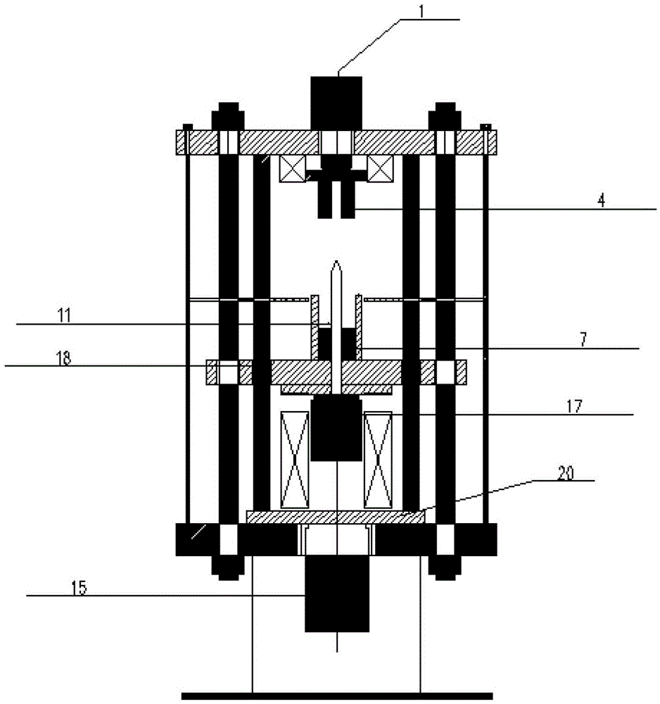
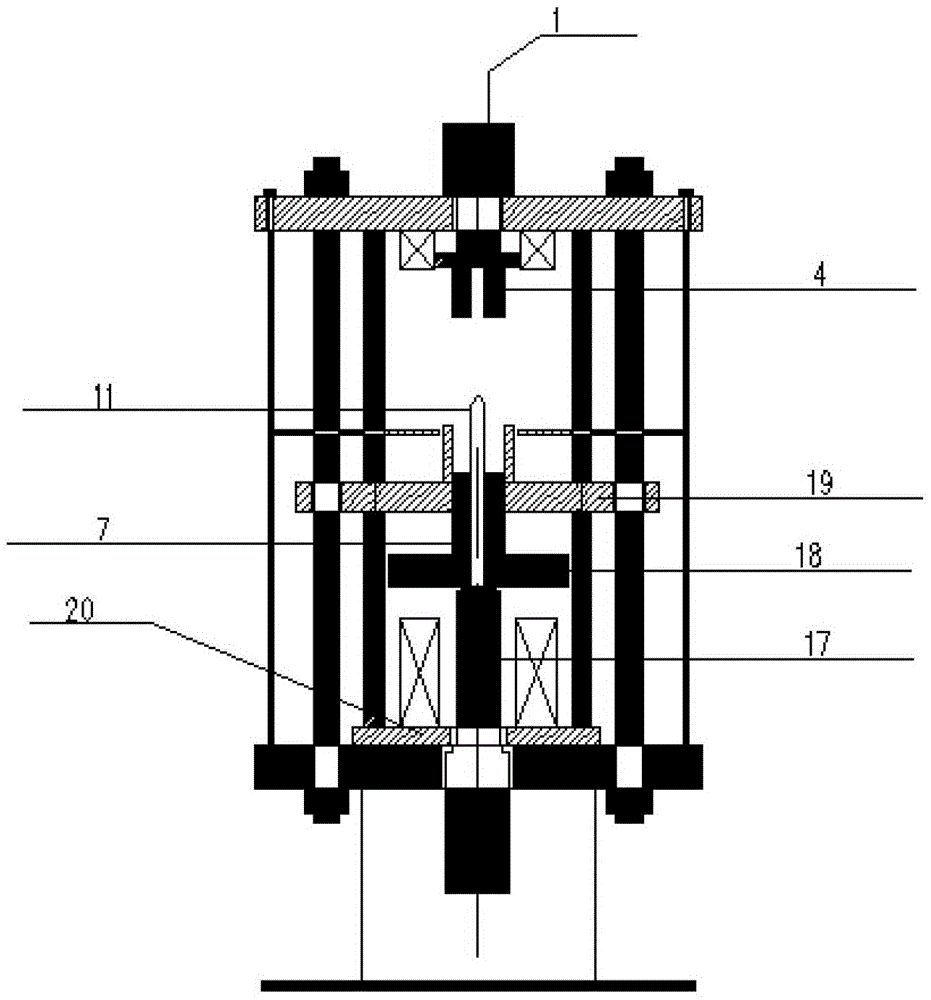
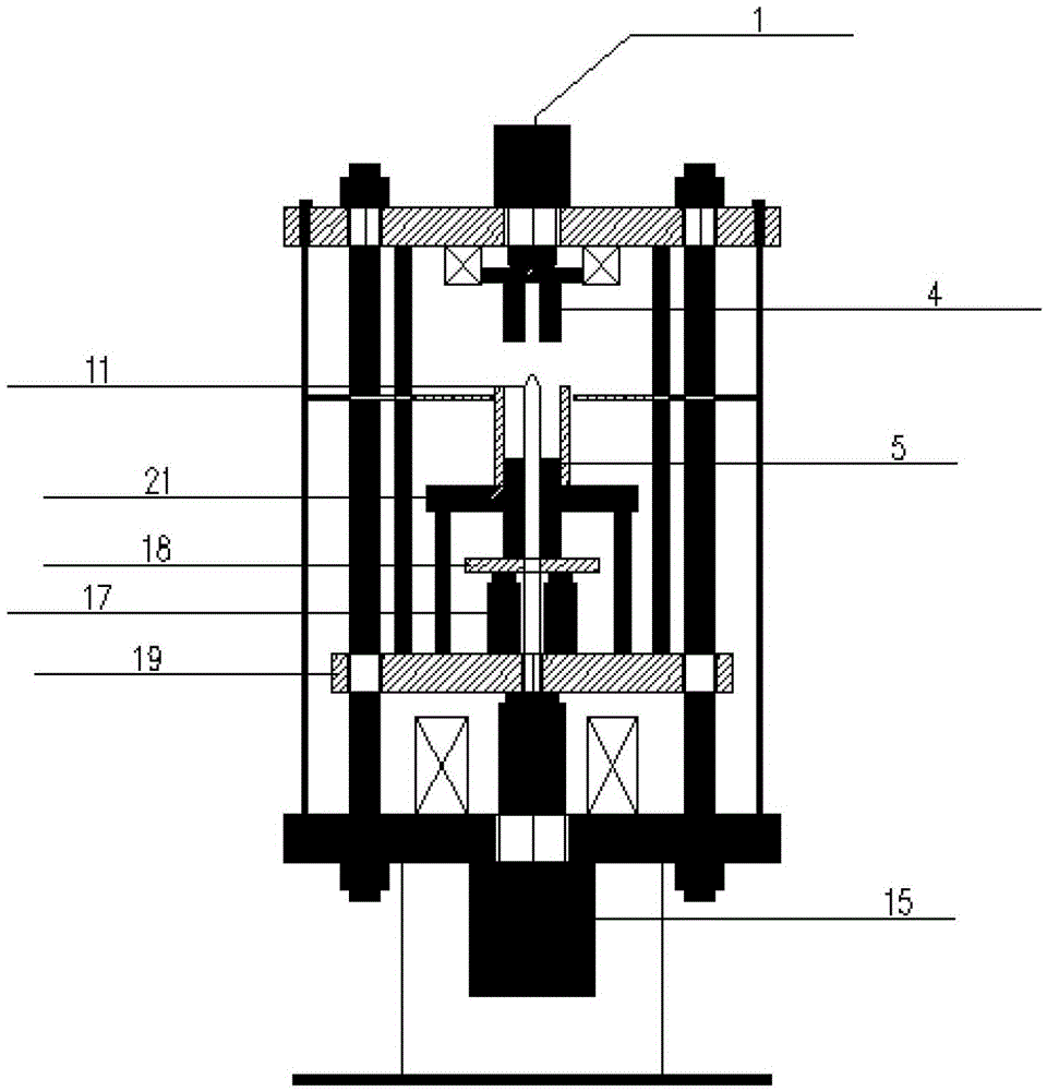
[0014] Such as figure 1 The main structure of the press: upper oil cylinder, lower oil cylinder, upper and lower wire packages, upper and lower beams, annular upper and lower punches, annular outer magnetic poles, outer wall of annular mold cavity, mandrel, press column, annular outer magnetic poles, Auxiliary oil cylinder, movable plate or / and fixed plate for structural support, frame and other main structures.

[0015] Such as figure 1 The preparation device of the radiation orientation ring shown: the annular outer magnetic pole with a certain thickness is close to the outside of the outer wall of the annular mold cav...


PUM


Abstract

The invention relates to a preparation device for a radial orientation permanent magnet ring. An outer magnetic pole is fixed on an outer magnetic pole connection support, and the thickness of the outer magnetic pole is far smaller than the height of a mold cavity. When exciting current passes through a coil, a radial magnetic field is generated in a ranged space of the mold cavity between a core rod and the outer magnetic pole, powder materials in the mold cavity are pushed by an oil cylinder to move vertically in a reciprocating mode, and therefore the power materials sequentially and circularly pass through the plane where the outer magnetic pole is located when the powder materials are pressed. When all the power materials sequentially and repeatedly pass through the plane where the outer magnetic pole is located and are pressed, the powder materials in a whole mold can be fully and uniformly oriented, radial orientation uniformity of the radial permanent magnet ring is greatly improved, meanwhile, axial uniformity of orientation degrees can also be improved, and the advantage is obvious especially for high radial rings. Besides, according to the preparation device for the radial orientation permanent magnet ring, the methods of manual mold release and automatic mold release can be adopted, operation is flexile, and the qualification rate of the pressed radial rings is greatly improved.

Description

technical field [0001] The invention relates to the field of manufacturing permanent magnet rings, in particular to a preparation device for radially oriented permanent magnet rings. Background technique [0002] The first one is to use the principle of repulsion of magnetic poles to generate a radiation orientation magnetic field mentioned in the application number 200510086882.9. The radiation magnetic field is generated by a pair of homopolar electromagnets. The DC or pulse current of each electromagnet generates N pole or S pole. Since the two electromagnets have the same polarity, they generate repelling magnetic lines of force. During the pressing process, the two The magnetic heads of the same polarity move towards the mold cavity at the same time, and form a radiating magnetic field through the magnetic permeable mold. This method guarantees the uniformity of the ring-shaped magnet in the circumferential direction to a certain extent, but the uniformity of the ring ...

Claims


Application Information

Patent Timeline
Patent Type & Authority Patents(China)
IPC IPC(8): H01F41/02H01F7/02B22F3/03
Inventor 王军文董生智廖超马世光
Owner ORIENT MAGNET TECH OMT
Why Eureka
Try Eureka