
Squeeze type juice squeezing mechanism

A squeezing and juicing technology, which is used in household machinery, kitchen utensils, household utensils, etc. for filtering food, can solve problems such as increasing work difficulty, feeding difficulties, affecting work efficiency, etc., and achieves low design and production costs. Easy cleaning and assembly, saving time and cost

Active Publication Date: 2013-06-05
GUANGDONG TONZE ELECTRIC CO LTD
View PDF6 Cites 13 Cited by
  • Summary
  • Abstract
  • Description
  • Claims
  • Application Information

AI Technical Summary

Problems solved by technology

But a problem of existing juice extractor is, because the profile of built-in screw rod and juice extracting chamber is all circular, and the axis of feed inlet and juice extracting chamber intersects simultaneously, this makes juice extractor feeding difficulty when squeezing, artificial The pressure is high, which affects work efficiency on the one hand, and increases the difficulty of work on the other hand
In addition, in the existing juicer, since the axial relative position between the built-in screw and the juicer cavity remains unchanged, this makes the juicer form particles of the same size when squeezing different materials. The machine cannot fully squeeze the material (such as watermelon) when squeezing some of the squeezed material with loose pulp and requires a finer particle size, which affects the juice yield; (such as apples), it is easy for the material to fill the gap between the pressing chamber and the built-in screw, and the slag cannot be discharged smoothly, which affects the juicing efficiency and the user experience is not high.

Method used


Image

  • Squeeze type juice squeezing mechanism
  • Squeeze type juice squeezing mechanism
  • Squeeze type juice squeezing mechanism

Examples


Embodiment 1

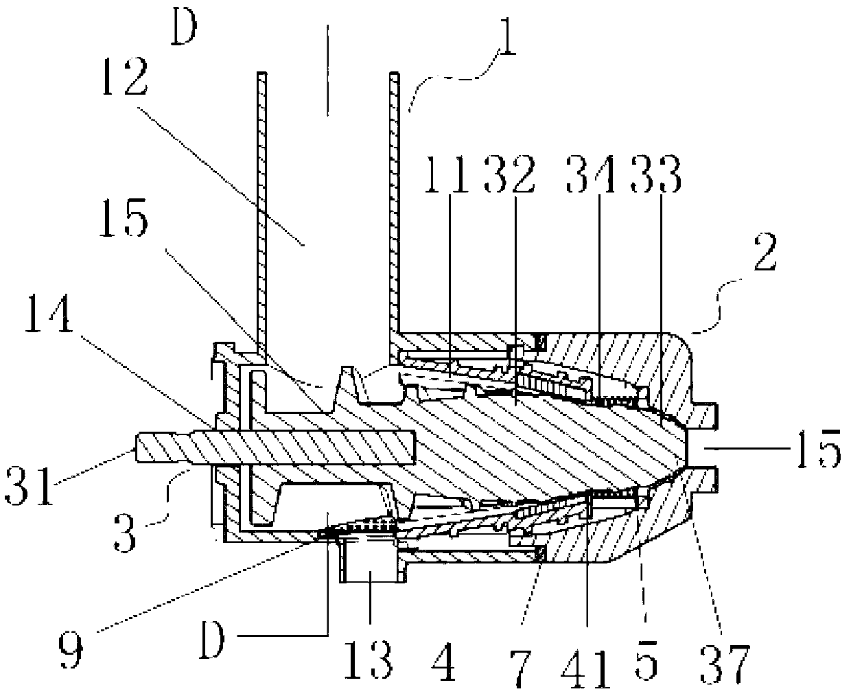
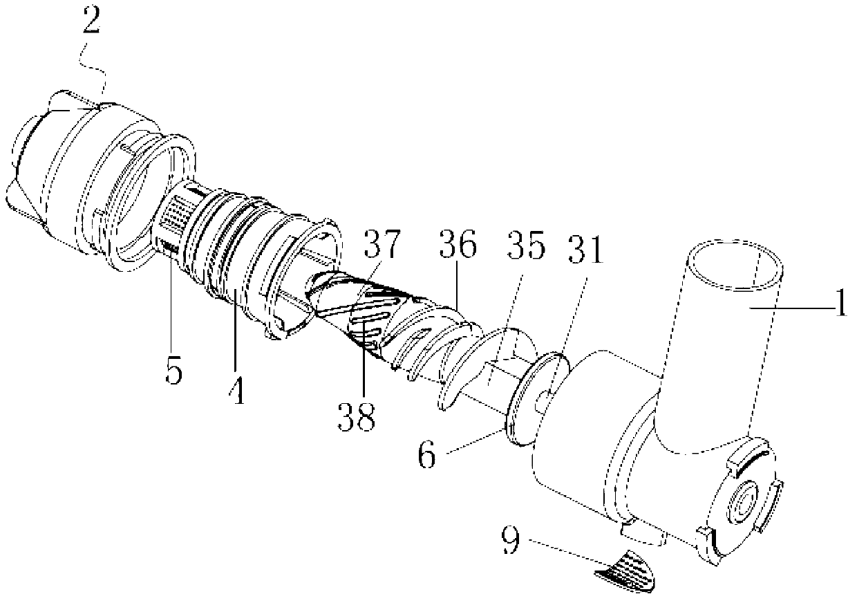
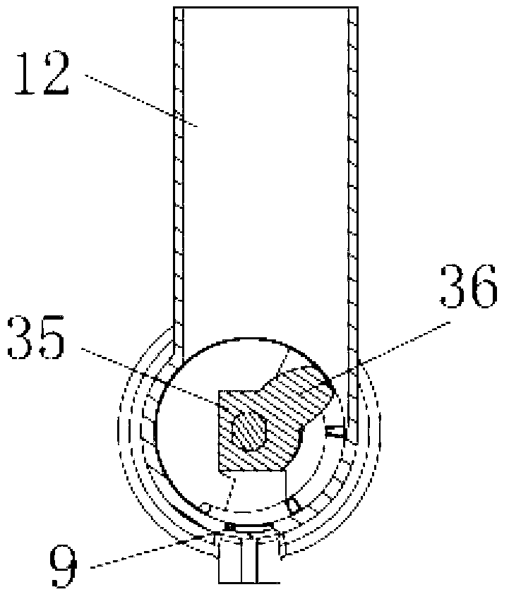
[0024] see Figure 1-Figure 3 , a squeeze-type juicing mechanism, including an outer shell 1, a screw 3 and a front cover 2 movably connected with the outer shell 1, the outer shell 1 and the front cover 2 are closed to form a cylindrical inner cavity, and the screw 3 Placed in the cylindrical inner cavity and reserved a gap for squeezing the juiced material between the outer shell 1 and the inner wall of the front cover 2, one end of the screw 3 runs through the end surface of the outer shell 1 and along the axial direction It is movable, and the screw rod 3 is respectively provided with a first limiting device and a second limiting device for restricting the screw rod 3 from exceeding the set active area in the axial direction.

[0025] In this embodiment, the outer casing 1 includes a juice extracting chamber 11, a feed chamber 12 and a juice outlet chamber 13 connected to the juice extracting chamber 11, the juice extracting chamber 11 forms a cylindrical structure with on...

Embodiment 2

[0031] The difference between this embodiment and Embodiment 1 is that the front cover 2 of this embodiment forms an inner cavity 21 near the end surface, and the inner cavity 21 communicates with the cylindrical inner cavity on the inside, and the inner cavity 21 is connected to the cylindrical inner cavity. A silicone pad 8 is provided at the joint of the cylindrical inner cavity. This setting acts as a water leak-proof.


PUM


Abstract

The invention relates to a squeeze type juice squeezing mechanism which comprises an outer shell body, a screw and a front cover movably connected with the outer shell body. The outer shell body is covered with the front cover to form a cylindrical inner cavity. The screw is placed in the cylindrical inner cavity and a gap used for squeezing juice squeezing materials is reserved between an inner wall of the front cover and the outer shell body. One end of the screw penetrates through an end face of the outer shell body and is capable of moving along the axial direction. A first limiting device and a second limiting device used for limiting the screw and preventing the screw from moving out of a set motion area when the screw moves along the axial direction are respectively arranged on the screw. According to the squeeze type juice squeezing mechanism, the screw has a certain degree of freedom when the screw moves along the axial direction so that the axial direction of the screw can be automatically adjusted according to the size of the juice squeezing materials and the juice squeezing mechanism is suitable for different kinds of juice squeezing materials. Meanwhile, a vane wheel main body portion is arranged to be a protruding prism and a feeding port is in tangency with the inner cavity of the outer shell body so that the materials can be cut effectively, feeding pressure of a juice squeezing machine is reduced and juice squeezing efficiency is improved.

Description

technical field [0001] The invention relates to the field of food processing, more specifically, to a squeezing type juice extraction mechanism. Background technique [0002] The structure of a typical juicer in the prior art usually includes a juicer cavity and a built-in screw driven by a motor, wherein the juicer cavity is provided with a feed port and a juice outlet, when the user puts the juicer material into the feed port , the juiced material is crushed by the high-speed rotating built-in screw in the juicer cavity to complete the juicer. But a problem of existing juice extractor is, because the profile of built-in screw rod and juice extracting chamber is all circular, and the axis of feed inlet and juice extracting chamber intersects simultaneously, this makes juice extractor feed difficulty when squeezing, manually The pressure is high, which affects work efficiency on the one hand, and increases work difficulty on the other hand. In addition, in the existing jui...

Claims


Application Information

Patent Timeline
Patent Type & Authority Applications(China)
IPC IPC(8): A47J19/00
Inventor 张义军卢俊杰钟华武
Owner GUANGDONG TONZE ELECTRIC CO LTD
Learn More