Conveying device for wood floor

A transmission device and wooden floor technology, which is applied in the field of wooden floor processing equipment components, can solve the problems of increased economic costs, achieve reduced economic costs, increase service life, and solve the effects of chain and track lockup and severe wear

Inactive Publication Date: 2013-06-05
苏州豪特景精密机械有限公司
View PDF10 Cites 0 Cited by
  • Summary
  • Abstract
  • Description
  • Claims
  • Application Information

AI Technical Summary

Problems solved by technology

Therefore, the higher the processing accuracy, the economic cost of the product will increase accordingly.

Method used


Image

  • Conveying device for wood floor
  • Conveying device for wood floor
  • Conveying device for wood floor

Examples


Embodiment Construction

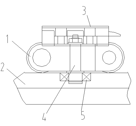
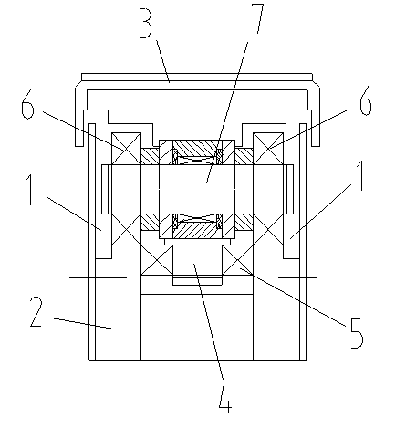
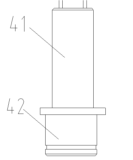
[0012] as attached figure 1 , 2 , 3 shows a wooden floor transmission device according to the present invention, comprising a chain, a guide rail 2, a support panel 3, a guide shaft 4, and a guide wheel 5; the chain moves along the guide rail 2; the support panel 3 is set On the chain; the upper end of the guide shaft 4 is arranged on the chain; the lower end of the guide shaft 4 is arranged in the guide rail 2; the upper end of the guide shaft 4 is fixed with a nut; the lower end of the guide shaft 4 is provided with a guide Wheel 5; the guide shaft 4 includes a main shaft 41 and an eccentric shaft 42; the main shaft 41 and the eccentric shaft 42 are arranged in parallel, and the central axes of the main shaft 41 and the eccentric shaft 42 are not collinear; the chain includes a plurality of A chain link unit; the chain is formed by connecting the chain link units end to end; the chain link unit includes a chain link 1, a bearing 6, and a rotating shaft 7; both ends of the r...


PUM


Abstract

The invention discloses a conveying device for a wood floor. The conveying device for the wood floor comprises chains, guide rails, a support panel, a guiding shaft and guiding wheels. The chains move along the guide rails. The support panel is arranged on the chains. The upper end of the guiding shaft is arranged on the chains. The lower end of the guiding shaft is arranged inside the guide rails. The upper end of the guiding shaft is fixed by nuts. Guiding wheels are arranged at the lower end of the guiding shaft. The guiding shaft comprises a main shaft and an eccentric shaft. The main shaft and the eccentric shaft are arranged in a parallel mode. The main shaft and the eccentric shaft are arranged in a non-collinear mode. According to the conveying device for the wood floor, economic cost is reduced by 20 percent. Meanwhile, the technical problems of locking and severe wear between the chains and the guide rails are effectively solved. Therefore, service life of the chains is increased by six months to ten months.

Description

technical field [0001] The invention relates to a transmission device, in particular to a wooden floor transmission device which effectively solves chain rail locking and severe wear, and belongs to the technical field of wooden floor processing equipment components. Background technique [0002] In the wood floor slotting tenon industry, at present, almost all models use a transmission device to transport workpieces. The transmission device includes guide rails, chains, and support panels; the chain moves along the guide rails; Described support panel is arranged on the chain; Because the length of chain, guide rail is generally all longer, often causes chain to be locked up in the guide rail inside or wears and teares because friction is too large and causes the bearing on the chain. For this phenomenon, many manufacturers improve the machining accuracy of the chain link and the central shaft; in this way, although the chain lock and wear can be reduced, it is often not wo...

Claims


Application Information

Patent Timeline
Patent Type & Authority Applications(China)
IPC IPC(8): B65G21/20B65G17/40
Inventor 孙俊贤
Owner 苏州豪特景精密机械有限公司
Why Eureka
Try Eureka