Rapid bridge detection method based on influence lines

A detection method and influence line technology are applied in the field of rapid bridge detection based on influence lines, which can solve the problems of high development cost, traffic blocking, and long time consumption.

Active Publication Date: 2017-09-05
CENT SOUTH UNIV
View PDF1 Cites 36 Cited by
  • Summary
  • Abstract
  • Description
  • Claims
  • Application Information

AI Technical Summary

Problems solved by technology

[0005] There are many test conditions in the existing bridge detection method, which takes a long time, may lead to traffic blockage for a long time, the requirements for the test environment are relatively strict, and the development cost is relatively high.

Method used


Image

  • Rapid bridge detection method based on influence lines
  • Rapid bridge detection method based on influence lines
  • Rapid bridge detection method based on influence lines

Examples


Embodiment 1

[0114] Combined with the 10a type I-beam, the rapid detection method of the bridge in the present invention is tested and studied. Bridge models such as Figure 5 As shown, the substructure of the model adopts prefabricated concrete pier, and the size of the pier is 0.2m×0.24m×0.6m. The upper structure is divided into 3 spans, namely the upper bridge span of 1.5m, the test span of 5m and the outgoing bridge span of 1.5m. The simply supported boundary condition of the I-beam is simulated by installing a smooth stainless steel member at the bottom of the beam. The two pieces of I-beams are independent of each other, and the transverse distance between their centerlines is 0.30m, which is consistent with the transverse wheelbase of the loaded vehicle.

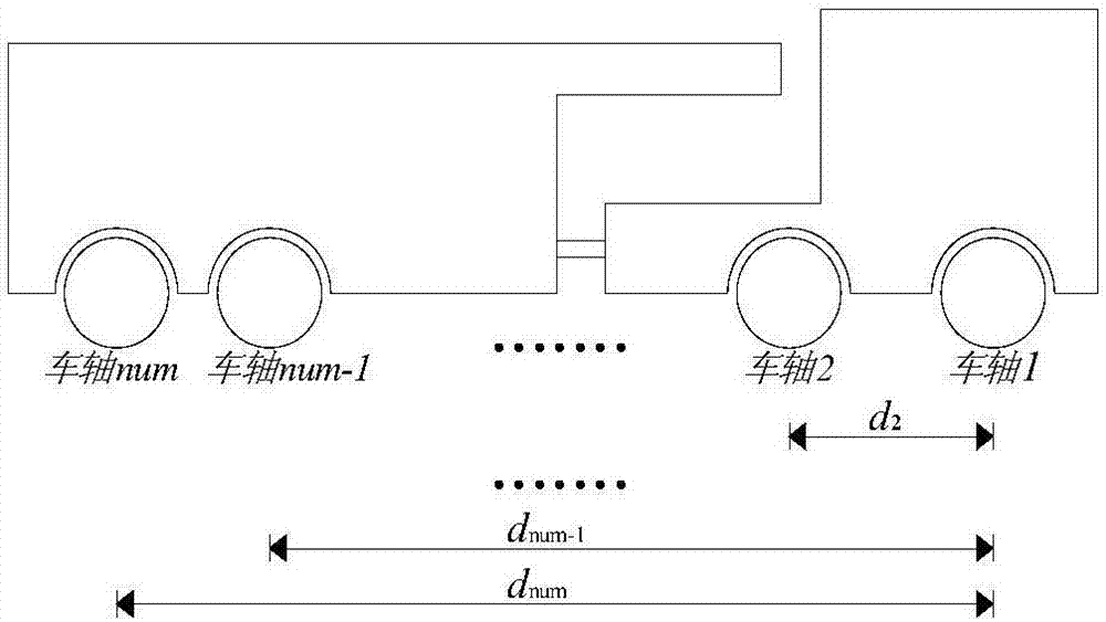
[0115] vehicle model such as Figure 4 , the body is designed as a cuboid, the size is 0.34m×0.56m×0.20m, and the total vehicle weight is 40kg. Since the two test beams are independent of each other, in order to ensure that th...

Embodiment 2

[0123] Taking the second span of a six-span prestressed concrete continuous box girder bridge as the experimental research object, the span of the bridge is 30m, and the clear width of the bridge deck is 20.85m. Cross section as Figure 12 shown.

[0124] The influence line test is measured by a single-vehicle sports car test. The main purpose of the sports car test is to obtain the corresponding data of the structure under the load of the moving vehicle, so as to extract the quasi-static influence line of the bridge, and provide a basis for the evolution of bridge structural characteristics and the evaluation of bearing capacity . The vehicle speed of the sports car test should not be too high, and the preferred value is 5km / h.

[0125] The static load test is loaded with 6 vehicles, and the technical parameters of the loaded vehicles are shown in Table 1.

[0126] Table 1 Loading Vehicle Technical Parameters

[0127]

[0128] The static load test is divided into three w...


PUM


Abstract

The invention relates to a rapid bridge detection method, which belongs to the technical field of civil engineering application. Firstly, a loading test vehicle with known axle load and wheelbase is adopted for loading to measure response of a test point; then, a method of adopting a specific function (piecewise polynomial and sine wave stacking) to fit the dynamic response of the test point is adopted to extract influence line information of the bridge; a tire-pavement stress distribution emprical formula is introduced to build a tire-pavement contact force trapezoid distribution model; in combination of the actual influence line information and the vehicle tire-pavement contact force distribution model, a linear superposition method is adopted to reconstruct bridge test point response information under different vehicle load combination effects, and thus, rapid bridge detection based on the influence lines is realized. Based on few driving tests on a single vehicle, the actual influence line information can be acquired rapidly and accurately, the bridge response information under different static load combination working conditions is reconstructed, rapid bridge detection is achieved, and the defects that the existing bridge detection method is long in consumed time, high in economic cost and long in traffic block time can be solved.

Description

technical field [0001] The invention relates to a rapid bridge detection method based on influence lines, belonging to the technical field of civil engineering applications. Background technique [0002] The response of the bridge structure is a function related to its basic physical parameters. Once its bearing capacity degrades, the physical parameters will inevitably change accordingly, so that the structural response under the same load will also change. Through the analysis and comparison of the measured response and theoretical calculation results, we can accurately understand the actual operating status of the bridge, and judge its safety and reliability. [0003] Commonly used bridge bearing capacity evaluation methods such as the static load test method apply a static load equivalent to the maximum design load value (such as: multiple vehicle loads) to a designated position on the bridge, and then evaluate the displacement, strain, and crack width of the bridge stru...

Claims


Application Information

Patent Timeline
Patent Type & Authority Applications(China)
IPC IPC(8): G01M5/00G06F19/00
CPCG01M5/0008G01M5/0041G16Z99/00
Inventor 王宁波黄天立时名扬沈炎张诗洁
Owner CENT SOUTH UNIV
Why Eureka
Try Eureka