Gantry crane travelling unit device

A technology for running parts and gantry cranes, which is applied in the directions of running mechanisms, transportation and packaging, load hanging components, etc. The effect of reliable parking, compact structure and safe driving

Inactive Publication Date: 2013-06-05
GEMAC ENG MACHINERY
View PDF9 Cites 4 Cited by
  • Summary
  • Abstract
  • Description
  • Claims
  • Application Information

AI Technical Summary

Problems solved by technology

However, the loose edge of the chain in this running part structure is very easy to collide with the surrounding structure, thus increasing the risk of chain wear and chain link falling off
At the same time, because the braking method of this running part is to only brake the gear disc at one end of the chain, the gear at the other end of the chain will continue to pull the chain under the action of inertia, maki

Method used


Image

  • Gantry crane travelling unit device
  • Gantry crane travelling unit device
  • Gantry crane travelling unit device

Examples


Embodiment Construction

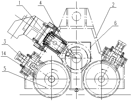
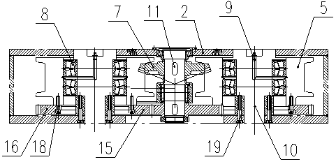
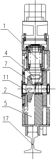
[0021] figure 1 Among them, the motor 1 and the brake cylinder 3 are installed on the outside of the box 2. The motor 1 directly drives the traveling wheel 5, and the transmission gears are arranged in a triangle, and are braked by the hydraulic cylinder 3. The small bevel gear 4 is connected to the output end of the motor 1 and meshes with the large bevel gear. The small bevel gear 4 and the large bevel gear form the high-speed stage of the whole running section. Small bevel gear 4 and big bevel gear outside have lubricating oil tank 6, the thin oil for bevel gear lubrication is housed inside. The power output end of the brake cylinder 3 is connected with the brake shoe 14 . The brake shoe 14 is on the upper side of the rim surface of the running wheel 5, and has a certain distance from the rim surface. When the brake cylinder 3 moves, the brake shoe 14 is pressed on the running wheel 5 to brake the running wheel. The effect of wheel 14 realizes the braking function of ru...


PUM


Abstract

The invention provides a gantry crane travelling unit device for the railway. A motor is arranged at an outer side of a casing. An output end of the motor is arranged in the casing. The output end of the motor is provided with a small bevel gear. The small bevel gear is in a meshing drive connection relationship with a large bevel gear in the casing. A transmission shaft and a travelling axle are installed in the casing. The large bevel gear is installed at one end of the transmission shaft and a transmission gear is installed at the other end of the transmission shaft. A travelling wheel is installed on the travelling axle. A travelling gear is directly or indirectly connected to the travelling wheel. The travelling wheel is in a drive connection relationship with the transmission shaft by the transmission gear and the travelling gear meshed with the transmission gear. The casing is provided with a hydraulic braking cylinder. A power output end of the hydraulic braking cylinder is connected to a brake shoe. The brake shoe which presses the marginal surface of the travelling wheel thereby braking the travelling wheel is arranged at an upper side of the marginal surface of the travelling wheel. The gantry crane travelling unit device has the advantages of compact structure, no strict requirements on a total framework structure of a gantry crane, strong generality, travelling safety and parking reliability.

Description

technical field [0001] The invention relates to a running part device of a gantry crane for overhauling which can walk on steel rails. Background technique [0002] The running part of the gantry crane is a device that can walk on the rails. It drives the running wheels to rotate through the motor, so that the entire gantry crane can move on the rails. [0003] At present, there are two main types of devices for the running part of the gantry crane in overhaul: one is that the motor drives the chain gear to rotate, and the chain gear transmits the power to the running wheel through the chain, so as to realize the walking function of the gantry crane. However, the loose edge of the chain in this running part structure is very easy to collide with the surrounding structure, thus increasing the risk of chain wear and chain link falling off. Simultaneously, because the braking method of this running part is to only brake the gear disc at one end of the chain, the gear at the ot...

Claims


Application Information

Patent Timeline
IPC IPC(8): B66C9/14B66C9/08
Inventor 杨林勇陈斌黄惠繁何干张麒
Owner GEMAC ENG MACHINERY
Why Eureka
Try Eureka