Building block
A technology of blocks and convex parts, which is applied to the pavement paved with prefabricated blocks, climate change adaptation, roads, etc. It can solve the problems of rough surface state of the sand cushion 42 and the inability to ensure the flatness of the joints, etc., and achieve excellent construction sex, the effect of maintaining planarity
- Summary
- Abstract
- Description
- Claims
- Application Information
AI Technical Summary
Problems solved by technology
Method used
Image

Examples
no. 1 Embodiment approach )
[0044] Below, refer to Figure 1 to Figure 6 A first embodiment in which the present invention is embodied as paving blocks laid on sidewalks, public places, etc. will be described.
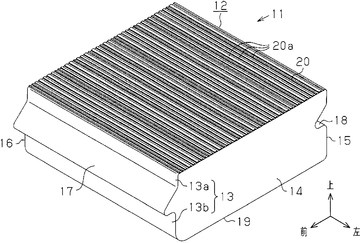
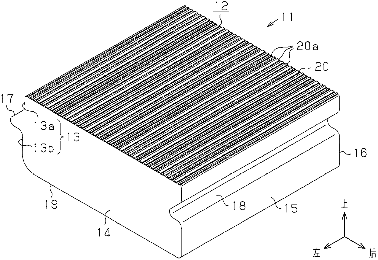
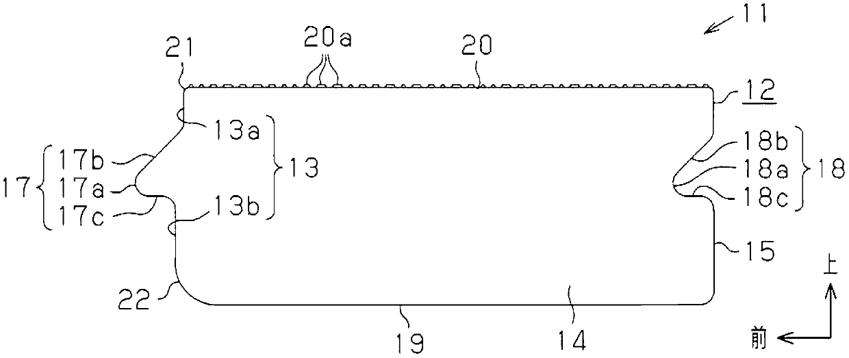
[0045] Such as figure 1 and figure 2 As shown, the block 11 of this embodiment has the block main body 12 formed in the shape of a flat plate, and this block main body 12 is comprised with concrete, and has a quadrangular shape in front view. A convex portion 17 is formed on the front side (one side) 13 of the four sides 13 , 14 , 15 , 16 of the rectangular laterally longer sides of the block main body 12 , and on the rear side opposite to the front side 13 The (other side) 15 is formed with a concave portion 18 having a shape corresponding to the convex portion 17 , that is, capable of fitting with the convex portion 17 formed on the front side 13 of another block 11 .
[0046] In addition, the convex portion 17 and the concave portion 18 extend along the lengthwise direction of the respect...
no. 2 Embodiment approach )
[0075] Next, refer to Figure 7 A second embodiment of the present invention will be described. In addition, compared with the first embodiment, the partial structures of the convex portion 17 and the concave portion 18 in other embodiments including the second embodiment to the sixth embodiment described below are different, but the other points are the same. structure. Therefore, in the description of each of the following embodiments, components that are different from those of the first embodiment will be mainly described, and the same reference numerals will be assigned to other identical structures, and repeated description will be omitted.
[0076] Additionally, if Figure 7 As shown, in the block 11 of the second embodiment, the convex underside contour portion 17c of the convex portion 17 formed on the front side 13 and the concave portion underside contour portion 18c of the concave portion 18 formed on the rear side 15 are located in the front and rear. It is dif...
no. 3 Embodiment approach )
[0080] Next, refer to Figure 8 A third embodiment of the present invention will be described.
[0081] Additionally, if Figure 8 As shown, in the block 11 of the third embodiment, the convex upper profile 17b of the convex 17 formed on the front side 13 and the concave upper profile 18b of the concave 18 formed on the rear side 15 are It differs from the configuration of the first embodiment in which these portions are formed in an oblique planar shape in that the front-rear direction is formed in a convexly curved shape inclined forward and downward. However, in the third embodiment, the convex portion upper contour portion 17b of the convex portion 17 and the concave portion upper contour portion 18b of the concave portion 18 are also formed in a shape inclined forward and downward in the front-rear direction of the longitudinal cross-sectional shape. This point is the same as that of the first embodiment.
[0082] Therefore, also in this third embodiment, the same effe...
PUM
 Abstract
Description
Claims
Application Information
 - R&D
- Intellectual Property
- Life Sciences
- Materials
- Tech Scout
- Unparalleled Data Quality
- Higher Quality Content
- 60% Fewer Hallucinations
Browse by: Latest US Patents, China's latest patents, Technical Efficacy Thesaurus, Application Domain, Technology Topic, Popular Technical Reports.
© 2025 PatSnap. All rights reserved.Legal|Privacy policy|Modern Slavery Act Transparency Statement|Sitemap|About US| Contact US: help@patsnap.com