
Exposed gear automatic lubricating device

An automatic lubrication and open gear technology, which is applied in the direction of gear lubrication/cooling, can solve the problems of easy intrusion of foreign debris, easy wear of gear teeth, and poor working environment of gears, so as to improve adaptability and installation flexibility. Satisfy the effect of lubricating

Inactive Publication Date: 2013-06-05
DONGHAI SILICON IND ENERGY SAVING TECHRES INST HENAN UNIV OF SCI & TECH
View PDF6 Cites 4 Cited by
  • Summary
  • Abstract
  • Description
  • Claims
  • Application Information

AI Technical Summary

Problems solved by technology

[0002] Open gear transmission refers to the transmission of gears in a non-confined space. Since the gear transmission does not have a dust cover or a casing, the gears are completely exposed to the outside, making the working environment of the gears relatively poor, which makes it easy for foreign debris to invade Therefore, the lubrication of the gear is particularly important. If the lubrication is not good, the gear teeth are easy to wear, which seriously affects the service life of the gear.
At present, there are mainly two methods for the lubrication of open gears. One is manual lubrication, that is, when the gears are driven, the lubrication is achieved by manually adding lubricating oil. This method is not easy to achieve long-term continuous lubrication of the gears, and manual The work intensity is high; the other is oil pump lubrication, which drives the oil pump with external power and sprays lubricating oil onto the tooth surface. Although this method can achieve long-term continuous lubrication of the gears, the oil pump needs to be connected to motors, electrical control components and other devices , high cost, and requires human control operation

Method used


Image

  • Exposed gear automatic lubricating device
  • Exposed gear automatic lubricating device

Examples


Embodiment Construction

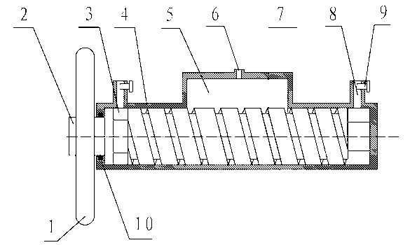
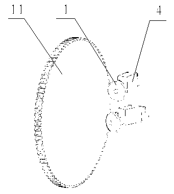
[0014] The embodiment of open gear automatic lubricating device of the present invention: as figure 1 , figure 2 As shown, it includes a closed casing 4, and the inner chamber of the casing 4 is composed of two circular hole sections extending in the left and right directions and a rectangular hole section connected in series at the middle position of the two circular hole sections, so that the two circular hole sections segment is divided into two fitting hole segments by a rectangular hole segment, and a rectangular cavity is formed between the two fitting hole segments. 5 communicates with the oil injection hole 6 through which lubricating oil can be injected into the oil storage chamber 5 . Rotating shaft 2 is inserted in the coaxial gap in the circular hole section. The rotating shaft 2 is a stepped shaft. The large diameter section is mounted on the top between the shell end covers at the two ports of the shell, and the small diameter section passes through the left sh...


PUM


Abstract

The invention discloses an exposed gear automatic lubricating device which comprises an airtight casing and a rotary shaft rotatably assembled in the casing. One end of the rotary shaft extends out of the casing, the extending portion is fixedly provided with a friction wheel in rotary fictional match with the end face of a gear. The peripheral face of the rotary shaft is provided with a helical structure which is axially screwed along the axial direction of the rotary shaft and used for conveying lubricating oil, the casing is provided with an adaptive hole section which is matched with the helical structure and used for achieving lubricating oil conveying along the axial direction of the rotary shaft when the rotary shaft rotates, and the casing is further provided with an oil storing cavity connected with the oil inlet end of the adaptive hole section and provided with an oil injecting hole, and an oil discharging cavity connected with the oil outlet end of the adaptive hole section and provided with an oil discharging hole. The exposed gear automatic lubricating device achieves lubricating oil supply by means of rotation of the gear, achieves automatic lubricating without other power, and is simple in structure and low in cost.

Description

technical field [0001] The invention relates to a lubricating device for gear transmission, in particular to an automatic lubricating device for open gears. Background technique [0002] Open gear transmission refers to the transmission of gears in a non-confined space. Since the gear transmission does not have a dust cover or a casing, the gears are completely exposed to the outside, making the working environment of the gears relatively poor, which makes it easy for foreign debris to invade Therefore, the lubrication of the gear is particularly important. If the lubrication is not good, the gear teeth are easily worn, which seriously affects the service life of the gear. At present, there are mainly two methods for the lubrication of open gears. One is manual lubrication, that is, when the gears are driven, the lubrication is achieved by manually adding lubricating oil. This method is not easy to achieve long-term continuous lubrication of the gears, and manual The work i...

Claims


Application Information

Patent Timeline
Patent Type & Authority Applications(China)
IPC IPC(8): F16H57/04
Inventor 杨建军魏冰阳马建伟杨宏斌
Owner DONGHAI SILICON IND ENERGY SAVING TECHRES INST HENAN UNIV OF SCI & TECH
Learn More