Disk drive device

A technology of disk drive device and tray, applied in the direction of recording information storage, instruments, etc., can solve the problem of inability to suppress resonance phenomenon, and achieve the effect of preventing warping deformation and restraining warping deformation

Inactive Publication Date: 2013-06-05
HITACHI CONSUMER ELECTRONICS CORP +1
View PDF7 Cites 2 Cited by
  • Summary
  • Abstract
  • Description
  • Claims
  • Application Information

AI Technical Summary

Problems solved by technology

However, this positioning mechanism is only an improvement of the guide mechanism for introducing and withdrawing the tray, and cannot suppress the resonance phenomenon that vibrates and displaces the central part of the tray in the width direction in the vertical direction.

Method used


Image

  • Disk drive device
  • Disk drive device
  • Disk drive device

Examples


Embodiment Construction

[0030] Hereinafter, one embodiment of the disk drive device of the present invention will be described based on the drawings. In the following, an optical disk drive device is taken as an example for description, but the structure of the main part can also be applied to other disk drive devices. In addition, the same code|symbol is attached|subjected to the same or equivalent structural part among each figure, and the overlapping description is abbreviate|omitted.

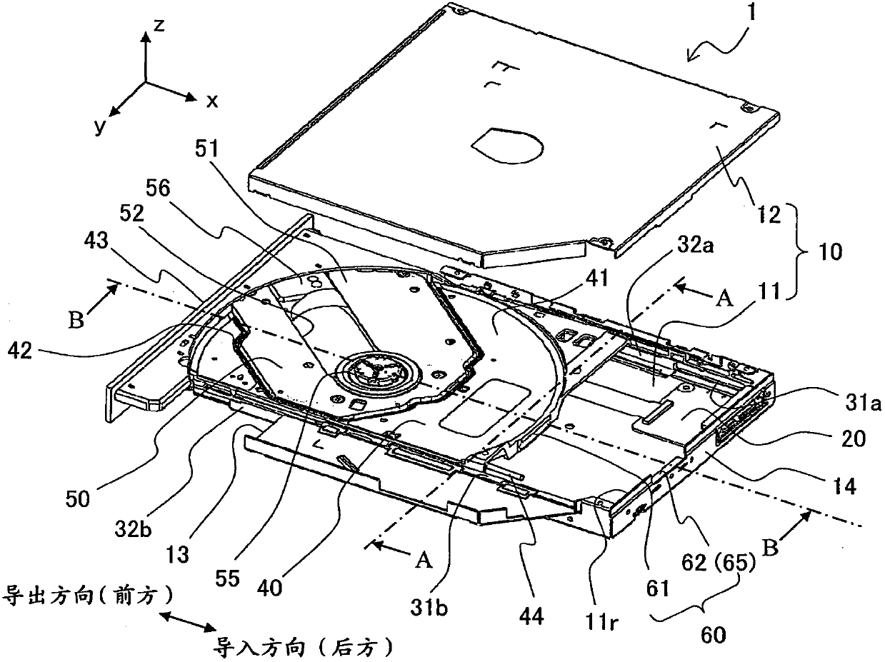
[0031] figure 1 It is a perspective view showing the configuration of an optical disk drive device according to an embodiment of the present invention.

[0032] The optical disk drive device 1 has a structure in which a tray 40 in a state where an optical disk is loaded can be introduced into and drawn out from a thin box-shaped casing (device casing) 10 .

[0033]Inside the casing 10, a circuit board 20 on which electronic components such as a connector and a CPU (Central Processing Unit) of each part of the con...


PUM


Abstract

A disk drive device that can prevent warping deformation in upward and downward directions of a disk tray and can prevent vibration in a warping deformation mode without producing a rattle vibration is provided. A disk drive device has a casing and a disk tray on which the spindle motor and the pickup are mounted; and a pair of parallel first and second guide mechanisms that slidably supports the disk tray so as to eject the disk tray from the casing to the outside. In the disk drive device, in a center part in a width direction along the disk mount surface of an introduction side distal end part of the disk tray, an introduction side abutment part having a groove section or a protruding portion is formed, and an inner part abutment part formed on an elastic member is installed on an inner side inner wall part.

Description

technical field [0001] The present invention relates to a disk drive device for recording and reproducing information, and more particularly to a tray-type disk drive device in which disks are mounted on trays drawn out from a device case and each tray is introduced into the device case. Background technique [0002] As a tray-type disk drive device, Patent Document 1 (Japanese Patent Application Laid-Open No. 2002-279717) discloses a structure in which, on the back side of the disk mounting surface (surface) of the tray, the height (thickness direction (vertical direction) )) is protrudingly provided with a rib-shaped contact portion, which is located in the central part of the width direction (left-right direction) on the introduction side (rear side in the front-rear direction) of the tray in the import-export direction (front-rear direction) of the tray, and in the tray The chassis on the fixed side, where the fixed position is opposite to the contact portion, is provide...

Claims


Application Information

Patent Timeline
Patent Type & Authority Applications(China)
IPC IPC(8): G11B17/02G11B17/053
CPCG11B17/056
Inventor 山崎达也西田育雄长峰秀行松本高路浅野晋矢山内良明木下康
Owner HITACHI CONSUMER ELECTRONICS CORP
Why Eureka
Try Eureka