Shift register

A shift register, potential technology, applied in static memory, digital memory information, instruments, etc., can solve problems such as instability, and achieve the effect of stable output potential and high elasticity

Active Publication Date: 2013-06-05
AU OPTRONICS CORP
View PDF6 Cites 7 Cited by
  • Summary
  • Abstract
  • Description
  • Claims
  • Application Information

AI Technical Summary

Problems solved by technology

However, since the on / off operation of the transistor requires a transition time, when the P-type transistors P1 and P2 are turned on / off, the potential on the output signal N is likely to be unstable.

Method used


Image

  • Shift register
  • Shift register
  • Shift register

Examples


Embodiment Construction

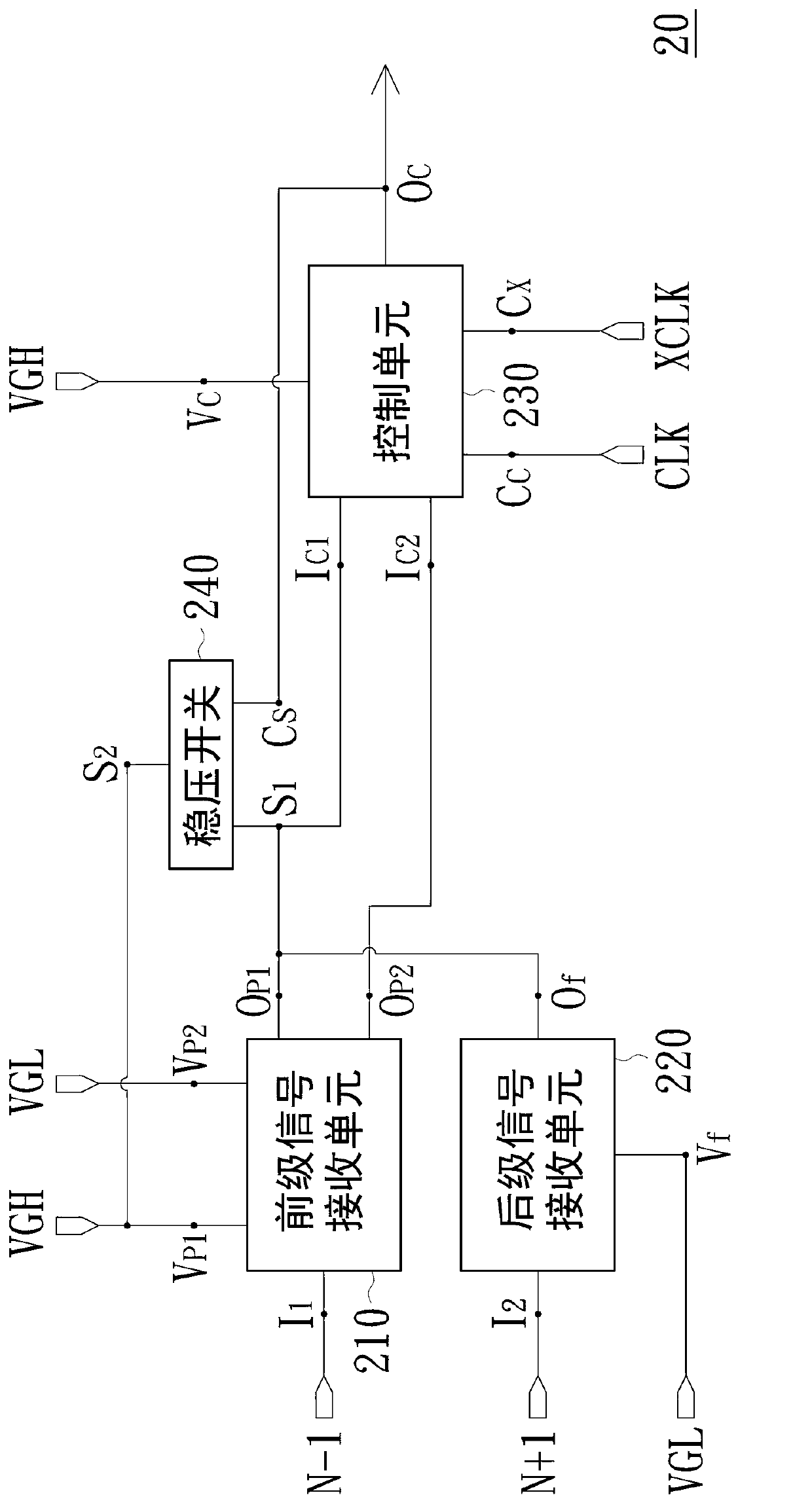
[0070] Please refer to figure 2 , which is a circuit block diagram of a shift register according to an embodiment of the present invention. In this embodiment, the shift register 20 includes a front-stage signal receiving unit 210 , a post-stage signal receiving unit 220 , a control unit 230 and a voltage stabilizing switch 240 . The pre-stage signal receiving unit 210 has a pre-stage signal input terminal I1, a pre-stage first preset potential input port VP1, a pre-stage second preset potential input port VP2, and a pre-stage first control signal output port OP1. And a second control signal output terminal OP2 of the previous stage. The previous-stage signal input terminal I1 receives the previous-stage signal N−1 outputted from the previous-stage shift register. The first preset potential input terminal VP1 of the previous stage is electrically coupled to the preset voltage source VGH. The pre-stage second preset potential input terminal VP2 is electrically coupled to th...


PUM


Abstract

The invention discloses a shift register, comprising a preceding-stage signal reception unit, a backward-stage signal reception unit, a control unit, and a voltage stabilization switch. The shift register controls signals to be output by virtue of continuous and stable voltage through the cooperative operation of circuits.

Description

technical field [0001] The present invention relates to a shift register, and in particular to a shift register (SHIFT REGISTER) with a stable output control voltage. Background technique [0002] The shift register is a widely used electronic component, and it can be seen in many electronic products. To put it simply, multiple shift register stages are generally connected together to form a shift register group, and an electronic signal is transmitted from the shift register of the previous stage to the shift register of the next stage. in the bit register. In this way, by shifting the delay time of signal transmission in the shift register group, an electronic signal can be made to perform correct functions at different times and at different positions. [0003] Please refer to Figure 1A and Figure 1B ,in Figure 1A is a circuit diagram of a common shift register, and Figure 1B It is a signal waveform diagram of each corresponding node of the shift register. Such a...

Claims


Application Information

Patent Timeline
Patent Type & Authority Applications(China)
IPC IPC(8): G11C19/28
CPCG11C19/28
Inventor 郑士嵩刘俊彦
Owner AU OPTRONICS CORP
Why Eureka
Try Eureka