
Traction inverting power module

A power module and inverter technology, applied in the electronic field, can solve the problem of large parasitic inductance of the circuit, achieve the effect of reducing parasitic inductance, simplifying the structure, and improving the convenience of maintenance

Inactive Publication Date: 2013-06-05
CRRC YONGJI ELECTRIC CO LTD
View PDF2 Cites 8 Cited by
  • Summary
  • Abstract
  • Description
  • Claims
  • Application Information

AI Technical Summary

Problems solved by technology

[0005] The invention provides a traction inverter power module to solve the defect of large parasitic inductance of the circuit in the prior art, reduce the parasitic inductance of the circuit, improve the reliability of the circuit, and at the same time improve the convenience of maintenance of the inverter power module

Method used


Image

  • Traction inverting power module
  • Traction inverting power module
  • Traction inverting power module

Examples


Embodiment Construction

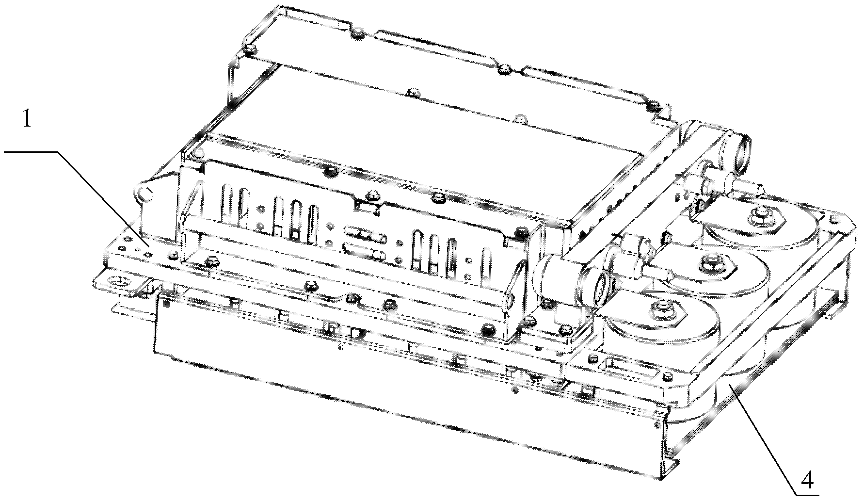
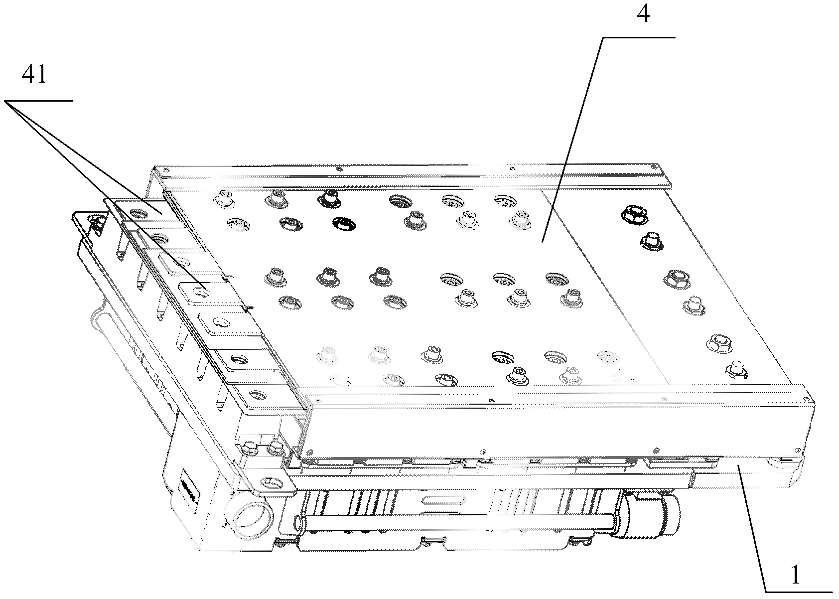
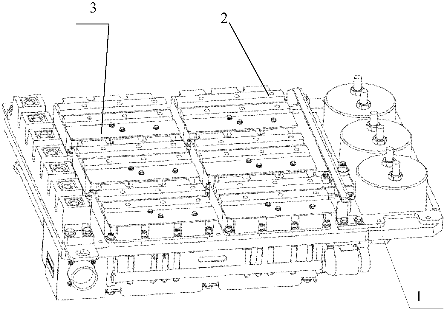
[0017] figure 1 Schematic diagram of the structure of the traction inverter power module provided by the embodiment of the present invention, figure 2 Schematic diagram of the structure of the traction inverter power module provided for the embodiment of the present invention Figure II , image 3 It is a schematic diagram of the traction inverter power module provided by the embodiment of the present invention without the composite busbar. The embodiment of the present invention provides a traction inverter power module, which includes a substrate 1, and one side of the substrate 1 is fixedly installed with multiple insulated grid double A polar transistor 2 and a drive protection plate 3 for providing drive protection for the insulated gate bipolar transistor 2, such as image 3 Shown is a schematic diagram of the traction inverter power module after the composite busbar is removed, the purpose is to clearly show the insulated gate bipolar transistor 2 and the drive prote...


PUM


Abstract

The invention provides a traction inverting power module. The traction inverting power module comprises a substrate, and a plurality of insulated gate bipolar transistors and driving protective plates are fixedly arranged on one side of substrate. The traction inverting power module further comprises a flat composite busbar. The traction inverting power module can also comprise a buffer capacitor and a discharge resister. The insulated gate bipolar transistors, the buffer capacitor and the discharge resister are connected with a main circuit through the busbar. According to the traction inverting power module, the flat composite busbar is integrated on the module, so that parasitic inductance in a circuit is reduced, the structure is simplified, and maintenance convenience of the traction inverting power module is improved, and the reliability of the circuit is improved at the same time.

Description

technical field [0001] The invention relates to electronic technology, in particular to a traction inverter power module. Background technique [0002] With the development of locomotive AC technology, converters using high-power IGBTs as switching elements are increasingly used. In order to facilitate the maintenance of the main circuit, multiple IGBT devices of one main circuit are installed and integrated to form a power module unit. [0003] The traction inverter power module of the locomotive is the core component of the traction system of the locomotive. After inverting the intermediate DC voltage through the three-phase circuit composed of IGBTs on the power module, the power conversion is completed through the inverter and the control system to provide power for the traction motor. Appropriate three-phase AC voltage. [0004] The existing traction inverter power module is not independent in structure, and it is not conducive to maintenance and replacement when the p...

Claims


Application Information

Patent Timeline
Patent Type & Authority Applications(China)
IPC IPC(8): H02M7/48
Inventor 张晋芳柴媛梁海刚陈宏
Owner CRRC YONGJI ELECTRIC CO LTD
Learn More