Solar focusing light and heat separation element

A technology for separating components and solar heat collectors, applied to optical components, electrical components, optics, etc., can solve the problem of low utilization rate of solar energy and achieve effective utilization

Inactive Publication Date: 2013-06-05
陕西科林能源发展股份有限公司
View PDF0 Cites 6 Cited by
  • Summary
  • Abstract
  • Description
  • Claims
  • Application Information

AI Technical Summary

Problems solved by technology

[0003] At present, the use of solar power generation is either solar photovoltaic power generation or solar thermal power generation. The fundamental difference is that different spectral bands of solar ene

Method used


Image

  • Solar focusing light and heat separation element
  • Solar focusing light and heat separation element

Examples


Embodiment Construction

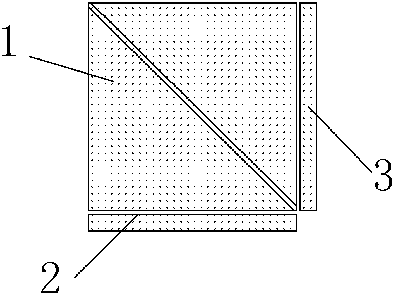
[0014] Such as figure 1 As shown, a solar photothermal separation element of the present invention includes a photothermal separator 1, a solar cell panel 2, and a solar thermal collector plate 3. The photothermal separator 1 is an optical coating cube, and the solar cell panel 2 Placed below the lower surface of the photothermal separator 1 , the solar collector plate 3 is placed outside the surface adjacent to the solar cell panel 2 .

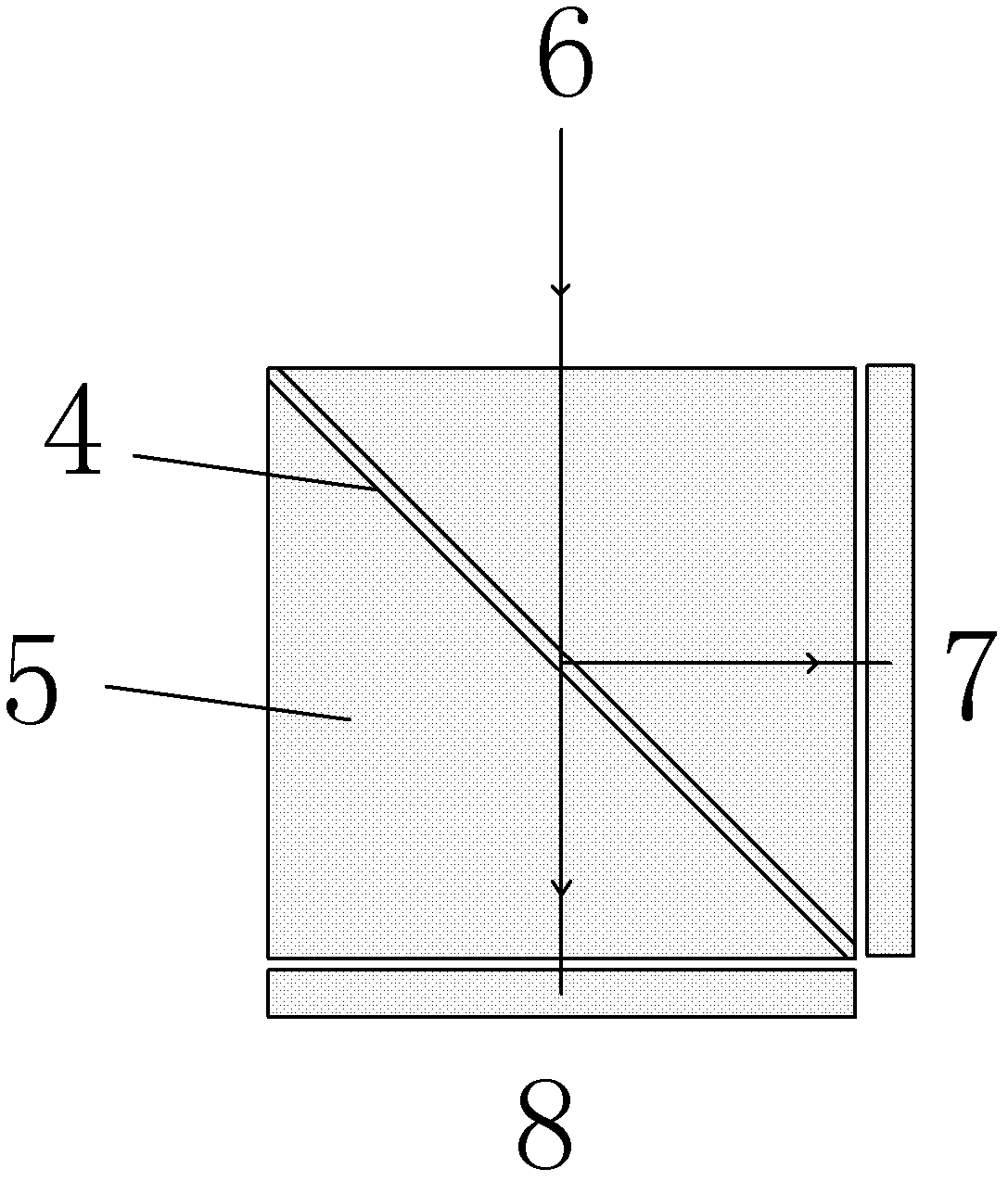
[0015] Such as figure 2 As shown, the photothermal separator 1 is formed by gluing two right-angled triangular prisms 5 , and the gluing surface is coated with an infrared reflective film 4 .

[0016] The working principle of the present invention is: when the solar ray 6 is incident on the photothermal separator 1, due to the effect of the infrared reflective film 4 on the photothermal separator 1, the infrared light 7 in the solar ray 6 is reflected to an exit surface , and the infrared light 7 is collected by the solar collector plate 3...


PUM


Abstract

The invention relates to a solar focusing light and heat separation element. The solar focusing light and heat separation element comprises a light and heat separator, a solar cell panel and a solar heat collection plate, wherein the light and heat separator is an optical film coating cube; the solar cell panel is arranged below the lower surface of the light and heat separator; the solar heat collection plate is arranged outside the surface which is adjacent to the solar cell panel 2; and the light and heat separator is formed by gluing two right-angle triangular prisms, and an infrared reflection film is plated on the gluing surface. According to the solar focusing light and heat separation element, visible light and infrared light in a solar spectrum are separated by utilizing the light and heat separator, and the solar cell panel receives the transmitted visible light, and power generation can be performed by utilizing the solar cell panel; and the solar heat collection plate receives the reflected infrared light, so that the hot end of a temperature difference power generation element is heated, so that power generation is performed by temperature difference. By utilizing the solar focusing light and heat separation element, solar photovoltaic power generation and solar heat power generation can be combined, so that solar energy is utilized effectively.

Description

technical field [0001] The invention relates to an element that utilizes an optical separator to simultaneously satisfy solar light power generation and thermal power generation. Background technique [0002] As a kind of nuclear fusion energy, solar energy will become an important part of the energy family as a new energy source with the increasing depletion of fossil fuels on the earth. At present, the use of solar energy by humans is becoming more and more common. In addition to passively used for indoor lighting, Building heating and domestic hot water, active solar energy utilization technology can convert solar energy into other forms of energy and obtain broader application prospects. Solar power generation is based on this, converting light energy into electrical energy, or conversion of light energy-thermal energy-electric energy. [0003] At present, the use of solar power generation is either solar photovoltaic power generation or solar thermal power generation. ...

Claims


Application Information

Patent Timeline
IPC IPC(8): H02N6/00H02N11/00G02B27/10G02B1/10H02S40/20
CPCY02E10/50
Inventor 杨向民许婷
Owner 陕西科林能源发展股份有限公司
Why Eureka
Try Eureka