No-voltage-type electronic touch switch
A touch switch, zero-voltage technology, applied in electronic switches, electrical components, pulse technology, etc., can solve the problems of affecting product exports, turning off lights and repairing electric shocks, and high component costs, achieving extended life, high reliability, and fewer components. Effect
- Summary
- Abstract
- Description
- Claims
- Application Information
AI Technical Summary
Problems solved by technology
Method used
Image
Examples
Embodiment 1
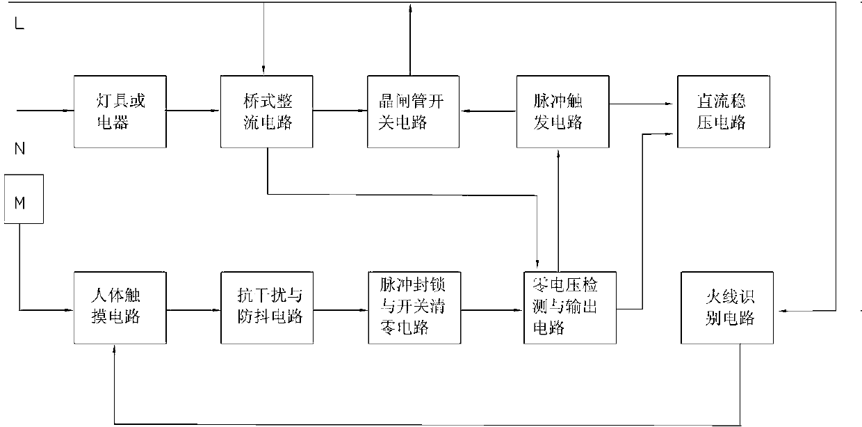
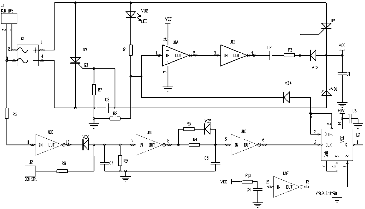
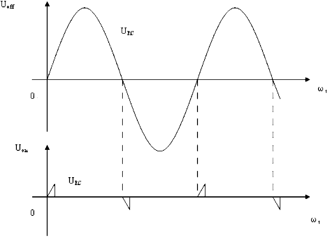
[0017] Such as figure 1 , figure 2 , image 3 As shown, the zero-voltage electronic touch switch of this embodiment includes a bridge rectifier circuit composed of a rectifier element Q1, a switch circuit composed of a power thyristor Q3, a pulse trigger circuit composed of a micro-trigger thyristor Q2, zero voltage detection and Output circuit, pulse blocking and power-on reset circuit, live wire identification circuit, human body touch circuit and DC voltage regulator circuit. An anti-interference and anti-vibration circuit is provided between the human body touch circuit and the pulse blocking circuit.
[0018] The zero-voltage detection and output circuit is placed between the pulse trigger circuit and the pulse blockade and power-on reset circuit, wherein the zero-voltage detection circuit is composed of a first resistor R1 and a second resistor R2 connected in series, and the zero-voltage output circuit is composed of a first It is composed of an integrated inverter ...
Embodiment 2
[0027] Such as Figure 4 , Figure 5 As shown, Embodiment 2 has a bridge rectifier circuit composed of rectifier element Q1 in Embodiment 1, a switch circuit composed of power thyristor Q3, a pulse trigger circuit composed of micro-trigger thyristor Q2, a zero voltage detection and output circuit, The live wire identification circuit, the human body touch circuit and the DC voltage stabilizing circuit differ in that: the pulse blockade circuit is composed of a monostable circuit composed of the seventh integrated inverter U1G with a delay circuit and a blockade diode VD4. The input end of the seven integrated inverter U 1G (the 13th pin of U 1G) is connected to the output end of the human body touch circuit (the 8th pin of the fourth integrated inverting U 1D) through the PNP transistor Q4, and the seventh integrated inverting The output end of U1G (the 12th pin of U1G) is connected with the input end (the 1st pin of U1A) of the first integrated inverter U1A of the zero volta...
PUM
 Abstract
Description
Claims
Application Information
 - R&D
- Intellectual Property
- Life Sciences
- Materials
- Tech Scout
- Unparalleled Data Quality
- Higher Quality Content
- 60% Fewer Hallucinations
Browse by: Latest US Patents, China's latest patents, Technical Efficacy Thesaurus, Application Domain, Technology Topic, Popular Technical Reports.
© 2025 PatSnap. All rights reserved.Legal|Privacy policy|Modern Slavery Act Transparency Statement|Sitemap|About US| Contact US: help@patsnap.com


