Excavator boom energy-saving system based on combined energy-saving hydraulic cylinder

An energy-saving system, hydraulic cylinder technology, applied in the direction of fluid pressure actuation system components, mechanically driven excavators/dredgers, earthmoving machines/shovels, etc. It is not conducive to problems such as mass production of enterprises, and achieves the effect of meeting the requirements of excavator working conditions, reducing the cost of modification, and having a wide range of applications.

Inactive Publication Date: 2022-02-01
CHANGSHA UNIVERSITY OF SCIENCE AND TECHNOLOGY
View PDF0 Cites 1 Cited by
  • Summary
  • Abstract
  • Description
  • Claims
  • Application Information

AI Technical Summary

Problems solved by technology

[0003] At present, there are many related researches on the energy-saving system of the excavator arm, but there are also some corresponding problems: First, most of the systems are relatively expensive and complicated, and the original hydraulic system or structure of the excavator needs to be modified in a large scale before they can be used. , which will increase the cost of the excavator during manufacture or modification, which is not conducive to mass production of enterprises; second, most research considerations are single. Although there have been combined energy-saving hydraulic cylinders for the excavator arm structure, there is no Research and improve the corresponding hydraulic system, or do not carry out comprehensive research on the improved hydraulic system and this energy-saving hydraulic cylinder to explore the energy-saving efficiency. When studying the energy-saving efficiency of the energy-saving system, the actual working conditions of the excavator are idealized, resulting in energy saving. The system can only be used for theoretical research, and cannot achieve the expected energy-saving effect in real application scenarios

Method used


Image

  • Excavator boom energy-saving system based on combined energy-saving hydraulic cylinder
  • Excavator boom energy-saving system based on combined energy-saving hydraulic cylinder
  • Excavator boom energy-saving system based on combined energy-saving hydraulic cylinder

Examples


Embodiment Construction

[0022] In order to further illustrate the technical solution of the present invention, it will be described in detail below in conjunction with the accompanying drawings.

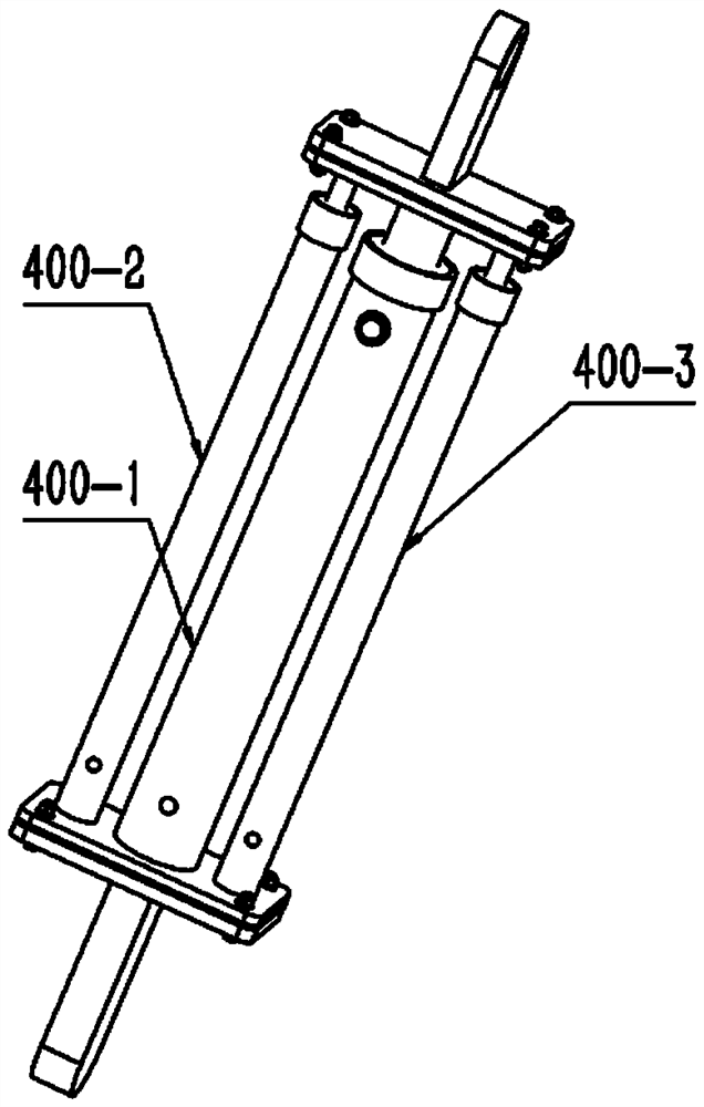
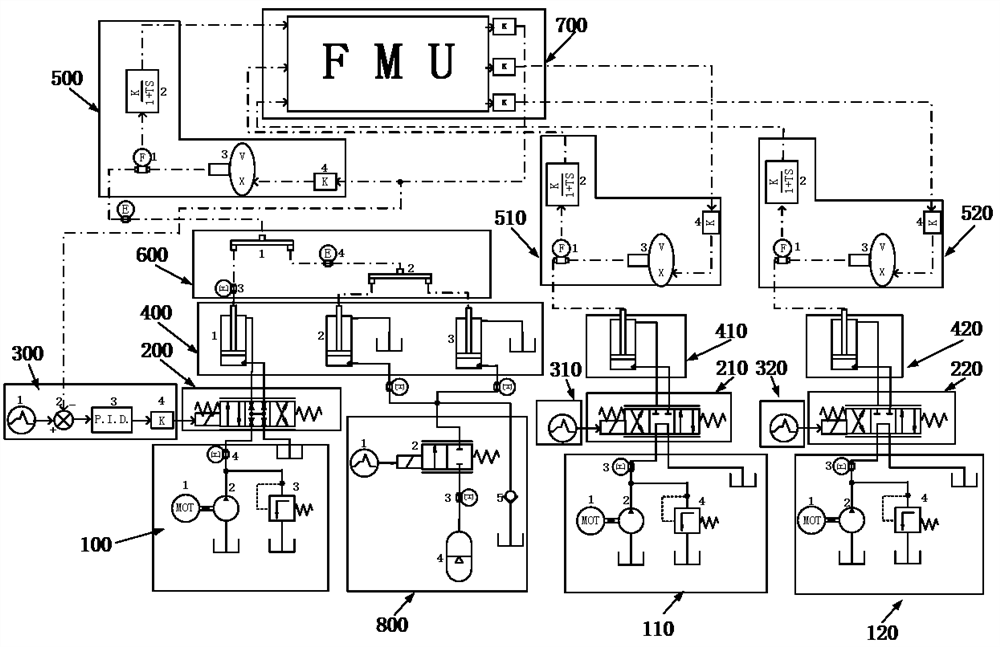
[0023] Refer to attached figure 2 An energy-saving system for an excavator arm based on a combined energy-saving hydraulic cylinder includes: the hydraulic pump output part is connected to the boom motor 100-1 and the boom hydraulic pump 100-2 to form the boom pressure energy output, and the boom is added to the output pipeline. The overflow valve 100-3 prevents the pressure of the boom hydraulic pipeline from being too high. The boom energy sensor 100-4 is located in the boom pressure energy output pipeline for measuring the total energy output of the boom; the arm motor 110-1 of the output part of the hydraulic pump It is connected with the stick hydraulic pump 110-2 to form the stick pressure energy output, and the stick relief valve 110-4 is added to the output pipeline to prevent the pressure of the s...


PUM


Abstract

The invention discloses an excavator boom energy-saving system based on a combined type energy-saving hydraulic cylinder. The system is characterized in that: an original hydraulic system of an excavator is transformed into the excavator movable arm energy-saving system with an energy-saving effect on the basis of a combined type energy-saving hydraulic cylinder structure. The system mainly comprises a hydraulic pump power output part, a reversing valve group part, a control part, a hydraulic cylinder group part, a hydraulic energy-saving system data transmission part, a linear mechanical node, an excavator FMU module and a movable arm energy-saving part. Energy is recycled when a movable arm descends, and energy is reutilized when the movable arm ascends; and the FMU module in the system can perform joint simulation on the system and an external excavator kinetic model. A certain energy-saving effect can be achieved without large-scale modification on an original hydraulic system and a movable arm structure, and a certain engineering application value is achieved.

Description

technical field [0001] The invention belongs to the field of engineering machinery hydraulic energy-saving and environmental protection, and relates to an energy-saving system for an excavator arm based on a combined energy-saving hydraulic cylinder. Background technique [0002] The energy saving and environmental protection of construction machinery has always been a focus of attention. In today's global warming and resource scarcity, it is urgent to improve the energy saving efficiency of construction machinery and reduce emissions. Excavator is a kind of common construction machinery, which is especially common in major infrastructure construction. The boom is one of the most important parts on the excavator. Its main function is to support the excavation of the bucket. When the excavator is working, the boom Frequent up and down actions will be carried out along with the working conditions, and the potential energy energy will be dissipated greatly. Therefore, it is of ...

Claims


Application Information

Patent Timeline
Patent Type & Authority Applications(China)
IPC IPC(8): F15B11/08F15B13/02F15B1/02F15B21/08E02F9/22E02F3/42
CPCF15B11/08F15B13/02F15B1/02F15B21/08E02F9/22E02F9/2217E02F3/42
Inventor 袁玉林贺湘宇谭丽莎蒋梦军张家彦刘琪
Owner CHANGSHA UNIVERSITY OF SCIENCE AND TECHNOLOGY
Why Eureka
Try Eureka