battery current sensor

A battery current and sensor technology, applied in voltage/current isolation, instruments, circuits, etc., can solve the problems of easy damage, bulky and expensive current sensors, etc., to achieve compact manufacturing, complex battery connections, and less susceptible to damage.

Active Publication Date: 2016-05-04
莱姆电子(中国)有限公司
View PDF5 Cites 0 Cited by
  • Summary
  • Abstract
  • Description
  • Claims
  • Application Information

AI Technical Summary

Problems solved by technology

[0004] Existing current sensors for battery post connection leads are bulky, expensive and, due to their installation around the connection lead, easily damaged, for example during installation or maintenance

Method used


Image

  • battery current sensor
  • battery current sensor

Examples


Embodiment Construction

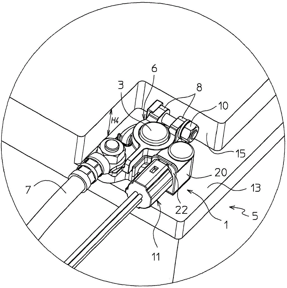
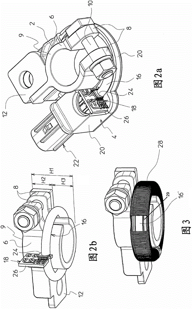
[0022] With reference to the drawings, a battery current sensor 1 according to an embodiment of the present invention includes a battery pole connection clamp part 2 and a current sensing part 4. The battery pole connecting clamp part can be installed around the battery pole 3 of the battery 5, where the battery 5 is generally a lead-acid type widely used in automobiles, backups or other applications. As is well known in itself, the battery pole can have standardized dimensions with a slightly tapered clamping surface. However, the present invention can also be used for other types of batteries or for cylindrical or slightly tapered battery terminals with non-standardized dimensions.

[0023] The battery pole connection clamp portion 2 includes a split tubular clamping body 6 having a flange 8 extending outwardly and radially from and generally from the free end of the clamping body, the flange having a flange received therethrough The clamping bolt 10 can be pressed together wi...


PUM


Abstract

A battery current sensor comprising a battery post connection clamp portion (2) and a current sensing portion (16), wherein the battery post connection clamp portion includes a terminal post (3) configured to clamp around a battery (5) The tubular clamping body, while the current sensing part includes a magnetic circuit (16) and a magnetic field sensor (18). The magnetic circuit comprises a magnetic core surrounding a tubular clamping body (6).

Description

Technical field [0001] The present invention relates to a current sensor for a battery, in particular to a current sensor for a lead-acid battery having poles connected to positive and negative leads, respectively. Background technique [0002] Lead-acid batteries are currently used in automotive and backup power applications and other applications. This battery has standardized connection poles for both positive and negative connections. The poles have a truncated cone shape with a small taper angle, and the complementary connection part generally includes a tubular connection clamp, which is compressed by a bolt. Flanges pressed together to fasten the tubular body to the connecting pole. Conductive cables used for power connections are usually welded, soldered, clamped or crimped to a tubular connection clamp. [0003] It is known to provide a current sensor around a conductive cable or in the connection area between the cable and the connection clamp in order to measure the cu...

Claims


Application Information

Patent Timeline
Patent Type & Authority Patents(China)
IPC IPC(8): H01R11/28G01R1/20G01R31/36G01R15/18G01R15/20
CPCG01R15/183G01R15/20G01R31/364G01R31/382H01R11/281H01R13/6683H01R2201/26G01R31/36
Inventor A·拉贝G·莱皮纳E·波切特
Owner 莱姆电子(中国)有限公司
Why Eureka
Try Eureka