Movable cutting edge mechanism of progressive stamping die

A movable and progressive die technology, applied in the field of electronic parts manufacturing equipment, can solve problems affecting product size, product use, punching step difference, etc., and achieve the effect of improving production efficiency, reducing machine tables, and occupying a small space

Active Publication Date: 2013-06-12
KUNSHAN XINTAILI PRECISION COMPONENTS CO LTD
View PDF7 Cites 2 Cited by
  • Summary
  • Abstract
  • Description
  • Claims
  • Application Information

AI Technical Summary

Problems solved by technology

[0005] like figure 1 As shown, this type of structure is more structurally specific than normal stamping products. The product is fully enclosed, and the connection position of the product carrier has been closed and blocked at the other end. If you continue to use the up and down straight-through punching method, it will inevitably be formed. The product is bruised, and

Method used


Image

  • Movable cutting edge mechanism of progressive stamping die
  • Movable cutting edge mechanism of progressive stamping die
  • Movable cutting edge mechanism of progressive stamping die

Examples


Embodiment Construction

[0018] The preferred embodiments of the present invention will be described in detail below in conjunction with the accompanying drawings, so that the advantages and features of the present invention can be more easily understood by those skilled in the art, so as to define the protection scope of the present invention more clearly.

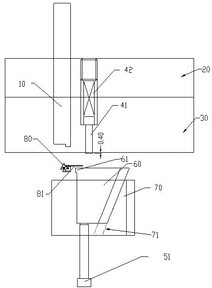
[0019] see image 3 , the embodiment of the present invention includes:

[0020] A movable knife-edge mechanism of a stamping progressive die, comprising: punching punch 10, middle die backing plate 20, middle template 30, upper die ejector pin 41, upper reset structure 42, lower die ejector pin 51, lower reset structure, Slider 60 and slider seat 70.

[0021] The middle mold backing plate 20 is connected to the middle formwork 30, the upper end of the upper mold ejector pin 41 is connected to the upper reset structure 42, and is installed in the middle mold backing plate 20 and the middle formwork 30, and the upper mold top The upper end of th...


PUM


Abstract

The invention discloses a movable cutting edge mechanism of a progressive stamping die. The movable cutting edge mechanism comprises a cutting punch, a middle die backing plate, a middle die plate, an upper die ejector pin, an upper restoring structure, a lower die ejector pin, a lower restoring structure, a sliding block and a sliding block seat. The movable cutting edge mechanism of the progressive stamping die can prevent a carrier from being frictionally deformed by finding a cutting point in the downward pressing process of a middle die plate through precise fitting between the sliding block and a pre-pressing ejector pin; and the sliding block can float up in an opened state, can diagonally move downwards in a closing process, can avoid the structure position of an already closed product and does not cause any problems such as collision and scratches to the product.

Description

technical field [0001] The invention relates to the field of electronic parts manufacturing equipment, in particular to a movable knife-edge mechanism of a stamping progressive die. Background technique [0002] With the continuous development of society, the pace of updating electronic products is accelerating, and supporting electronic components are gradually moving towards standardized and general-purpose mass production. Most product structures are finalized, space is limited, and stamping technology also requires continuous improvement to meet various product structures. [0003] According to the product structure needs to develop stamping dies that meet the application, and the standardized products have product size and structure due to their small size, so the stamping products are small in size and have strict requirements. The internal molding structure of the existing mold cannot meet the product design structure and precision requirements, resulting in a certain...

Claims


Application Information

Patent Timeline
IPC IPC(8): B21D28/14
Inventor 张晓亮
Owner KUNSHAN XINTAILI PRECISION COMPONENTS CO LTD
Why Eureka
Try Eureka