Unhooking device controlled by steering engine

A decoupler and steering gear technology, which is applied to aircraft parts, parachutes, transportation and packaging, etc., can solve the problems of reduced work efficiency, large volume and mass, and increased manpower, and achieve the effects of reduced manpower assistance, small size, and reliable decoupling

Inactive Publication Date: 2015-05-27
SHANGHAI UNIV
View PDF3 Cites 0 Cited by
  • Summary
  • Abstract
  • Description
  • Claims
  • Application Information

AI Technical Summary

Problems solved by technology

[0003] Traditional decoupling devices can be divided into two categories at present, one is the decoupling device that requires manual operation, this type of decoupling device requires manual hooking and unhooking, which increases manpower and reduces work efficiency
The other type is a hydraulically controlled uncoupling device, which uses a hydraulic system to control the decoupling of the hook. The greater the lifting weight, the larger the required oil cylinder, the greater the volume and mass, and the higher the cost

Method used


Image

  • Unhooking device controlled by steering engine
  • Unhooking device controlled by steering engine
  • Unhooking device controlled by steering engine

Examples


Embodiment 1

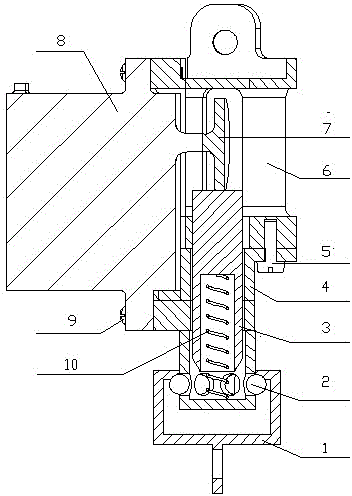
[0021] see figure 1 , the uncoupling device controlled by the steering gear includes a lifting ring (1) and a decoupling mechanism, which is characterized in that the decoupling mechanism is a ball coupling type decoupling mechanism; a steering wheel is fixedly installed on the output shaft of a steering gear (8) (7), the wheel hub profile of the steering wheel (7) interferes with driving a control mandrel (3) in the ball coupling type uncoupling mechanism, so as to realize the locking and uncoupling of the suspension ring (1).

Embodiment 2

[0023] see Figure 1 to Figure 5 , this embodiment is basically the same as Embodiment 1, and the special case is as follows:

[0024] The ball locking type uncoupling mechanism includes: a hollow shaft (4), 2 to 6 balls (2), a spring (10), a control mandrel (3) and a semi-hollow column (6). The lifting ring (1) and the hollow shaft (4) are coaxially installed, the balls (2) move in the circumferentially uniform holes under the hollow shaft (4), the spring (10) is coaxial with the control spindle (3), and the length Half of it extends into the inner hole of the lower part of the control mandrel (3), and the control mandrel (3) is coaxial with the hollow shaft (4), and the hollow shaft (4) and the semi-hollow column (6) pass three hexagon head screws ( 5) are connected with each other; there is a boss at the connecting end of the hollow shaft (4) and the semi-hollow column (6), on which the steering gear (8) is connected with the steering gear (8) through the round head screw ...

Embodiment 3

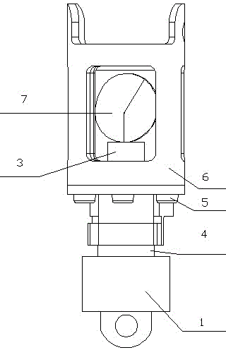
[0029] Such as figure 1 , figure 2 As shown, the uncoupling device controlled by the steering gear consists of a lifting ring (1), a hollow shaft (4), a ball (2), a spring (10), a control mandrel (3), a semi-hollow column (6), a steering gear (8 ) and the steering wheel (7), the upper end of the suspension ring (1) is connected with the hollow shaft (4) through the ball (2), half of the ball (2) is stuck in the hollow shaft (4), and the other half passes through the upper end of the suspension ring (1) The circular arc is connected with the suspension ring (1). The hollow shaft (4) and the semi-hollow column (6) are connected by three hexagon head screws (5). The round head screw (9) is connected with the steering gear (8), two-thirds of the spring (10) is put into the control mandrel (3), and the head of the spring (10) is in contact with the hollow bottom of the hollow shaft (4) , the outer solid part of the control mandrel (3) is in contact with the steering wheel (7) o...


PUM


Abstract

The invention relates to an unhooking device controlled by a steering engine. The unhooking device comprises a flying ring and an unhooking mechanism, and is characterized in that the unhooking mechanism is a ball interlocking mechanism; a steering wheel is fixedly mounted on the output shaft of the steering engine, and the profile of the hub of the steering wheel drives one control central spindle in the ball interlocking mechanism in a propping manner, so that locking and unhooking to the flying ring are realized. The unhooking device not only meets the function requirements of safe hoisting and smooth release, is controlled by the steering engine, combines machinery and power, reduces assisted human, is time-saving and labor-saving, has a small size and a simple control signal, and is convenient in installation and use and reliable in unhooking.

Description

technical field [0001] The invention relates to a light decoupling device which can be used for parachutes, model airplanes and the like and needs automatic control, in particular to a decoupling device controlled by a steering gear. Background technique [0002] The invention relates to a light uncoupling device which can be widely used in parachutes, model airplanes and the like and requires automatic control. The special function of the device is that under the control of the steering gear, the decoupling function under load conditions can be realized. [0003] Traditional decoupling devices can be divided into two categories at present, one is the decoupling device that requires manual operation, this type of decoupling device requires manual hooking and unhooking, which increases manpower and reduces work efficiency. The other type is a hydraulically controlled uncoupling device. This type of uncoupling device uses a hydraulic system to control the decoupling of...

Claims


Application Information

Patent Timeline
Patent Type & Authority Patents(China)
IPC IPC(8): B64D17/22
Inventor 饶进军刘甜张嘉毅
Owner SHANGHAI UNIV
Why Eureka
Try Eureka