
Conveying apparatus

A technology for handling devices and objects, which is applied in the direction of transportation and packaging, conveyor objects, etc., and can solve the problems of unsmooth and complicated handover of the objects being carried

Active Publication Date: 2013-06-12
NAKANISHI METAL WORKS CO LTD
View PDF6 Cites 3 Cited by
  • Summary
  • Abstract
  • Description
  • Claims
  • Application Information

AI Technical Summary

Problems solved by technology

[0011] Therefore, when the conveyed object is transferred between the elevator and the carrier, it is necessary to perform the opening and closing action of the carrier hanger and the lifting action of the elevator. Handover is not smooth enough, more complex operations need to be performed

Method used


Image

  • Conveying apparatus
  • Conveying apparatus
  • Conveying apparatus

Examples


Embodiment Construction

[0029] Hereinafter, embodiments of the present invention will be described in detail with reference to the drawings, but the present invention is not limited to the forms shown in the drawings and includes all embodiments that satisfy the requirements described in the claims. In addition, in this specification, the conveyance direction (refer to the arrow F in the figure) is regarded as the front, and the left and right are divided according to this. And, look at the main view from the left.

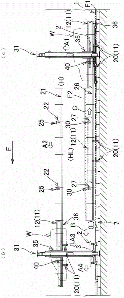
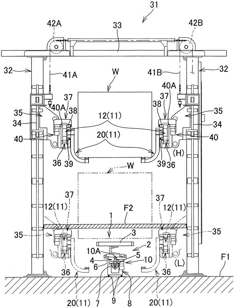
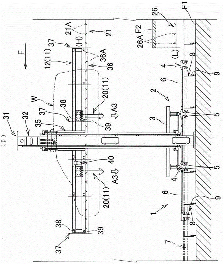
[0030] Figure 1 to Figure 7 It is a schematic diagram showing the structure of the conveying device according to the embodiment of the present invention. figure 1 To represent the front view around the ascending line, figure 2 To see the figure of the lifter from the rear, image 3 is an enlarged front view around the downstream side riser, Figure 4 is a perspective view of the carrier, Figure 5 It is a front view showing the transfer of objects on the downstream side of the asc...


PUM


Abstract

The invention provides a conveying apparatus. The conveying apparatus has a hoist work line HL on the way of a path for conveying an object W to be conveyed on a truck with a floor conveyer 1. On the hoist work line HL, the object W to be conveyed on a truck 2 is replaced to a carrier 11 for work. The carrier 11 is provided with a pair of right and left frame bodies 12 and a receiving member. The conveying apparatus is installed with a fixed rail 21 for a conveying line in a high position H and with a friction roller type drive unit 25 for driving an actual carrier 11 to the downstream side. Further, the conveying apparatus is installed with a fixed rail 26 for a return line in a low position L immediately below the fixed rail 21 and with a friction roller type drive unit 30 for driving an empty carrier 11 to the upstream side. In addition, drop lifters 31, each of which is mounted with a friction roller type drive unit 40 for driving a carrier 11 supported by a hoisting and lowering rail 36 in the longitudinal direction, are installed on the upstream side (a) and the downstream side (b) of the hoist work line HL so that the hoisting and lowering rails 36 are connected to the fixed rails, respectively.

Description

[0001] The present invention is a divisional application of the applicant's patent application whose filing date is February 26, 2009, Chinese patent application number is 200910008350.1, and the title of the invention is "handling device". technical field [0002] The present invention relates to a conveying device, which has the function of lifting the conveyed object from the dolly to the carrier in the middle of the path in which the conveyed object is loaded on a shared trolley and conveyed by a floor conveyor. The ascending operation line for the operation in the state. Background technique [0003] The new car coating process of automobiles includes electrodeposition coating process, mid-coat coating process, and final coating process. After each painting process, there is a drying process using a drying oven. Generally speaking, electrodeposition coating The vehicle body transportation in the process needs to be immersed in the treatment tank, so it is carried out by...

Claims


Application Information

Patent Timeline
Patent Type & Authority Applications(China)
IPC IPC(8): B65G47/52
Inventor 佐藤浩幸
Owner NAKANISHI METAL WORKS CO LTD
Learn More