Supercharge Your Innovation With Domain-Expert AI Agents!

Take-up device and method for heat treatment of bead wires

A wire take-up device and bead steel wire technology, applied in heat treatment furnaces, heat treatment equipment, furnaces, etc., can solve the problems of inability to observe the surface quality of steel wires, disordered equipment investment, and complicated maintenance

Inactive Publication Date: 2013-06-12
ZHANGJIAGANG SHENGDA STEEL ROPE
View PDF7 Cites 4 Cited by
  • Summary
  • Abstract
  • Description
  • Claims
  • Application Information

AI Technical Summary

Problems solved by technology

In the traditional production process, the I-wheel take-up method is generally used. In the actual production process, the surface quality of the phosphating steel wire cannot be observed in this way, or the failure of the I-wheel arrangement leads to disorder, and the equipment investment is large and the maintenance is more complicated.

Method used


Image

  • Take-up device and method for heat treatment of bead wires
  • Take-up device and method for heat treatment of bead wires
  • Take-up device and method for heat treatment of bead wires

Examples


Embodiment 1

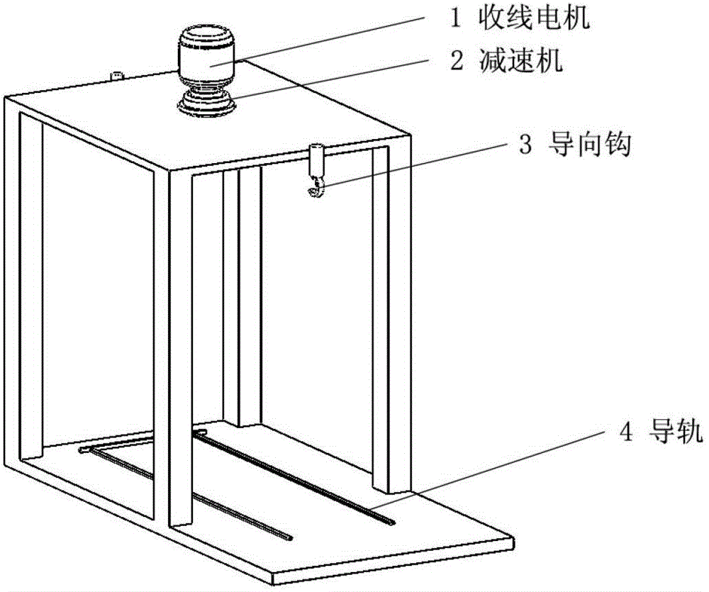
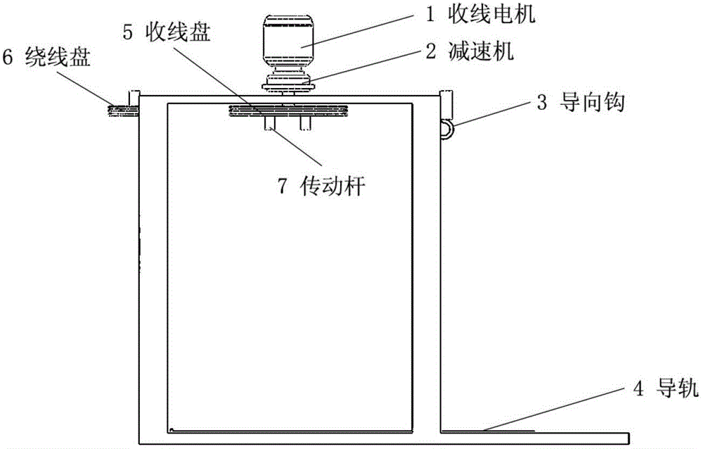
[0029] Such as Figure 1-Figure 3 As shown, after the steel wire enters the take-up device, it first enters the winding reel 6 and the take-up reel 5, and through the guide hook 3, the steel wire is taken up on the take-up frame 9. The winding reel 6 and the take-up reel 5 adopt double-layer V-groove design, and the steel wire is wound twice on the winding reel 6 and the take-up reel 5, so as to ensure sufficient friction between the steel wire and the take-up reel 5, and increase the resistance to the steel wire. traction and prevent slipping. The traction of this device is that the top is a take-up motor 1, which adopts a 2.2KW torque three-phase asynchronous motor, and the take-up motor 1 transmits power to the reducer 2 to obtain a larger torque. Then by driving the transmission rod 7 on the wire take-up reel 5, the transmission rod 7 is rotated after contacting the baffle plate 8 on the wire collection frame 9, and the wire collection frame 9 conflicts with the fixed col...

example 2

[0031] On the basis of the above examples, if Figure 1 to Figure 3 As shown, during the operation of the steel wire, as the number of steel wires on the wire receiving frame 9 increases, the output speed of the wire receiving motor 1 will gradually decrease. By adopting the AC frequency conversion speed regulation technology, the speed of the steel wire in the heat treatment process is guaranteed to be moderate, preventing the steel wire from Uneven wire cleaner performance due to speed fluctuations.

example 3

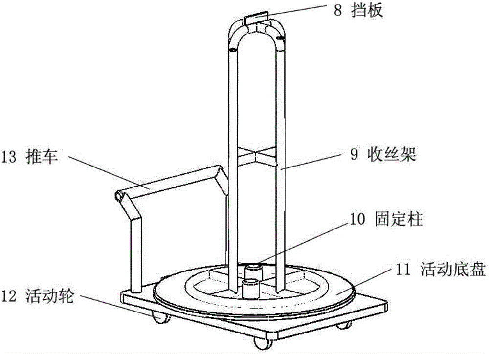
[0033] On the basis of the above examples, if Figure 1 to Figure 3 As shown, during the wire take-up process, the steel wire automatically falls onto the wire take-up frame 9 by its own weight. When the steel wire reaches the required weight, the lower movable wheel 12 is driven by pulling the cart 13, and the cart 13 is pulled out of the wire take-up device. , then the steel wire is hung out together with the wire receiving rack 9, and then other empty wire receiving racks 9 are placed on the movable chassis 11, and by pushing the trolley 13, the movable wheel 12 below it enters the wire receiving device along the guide rail 4, that is, Continuous heat treatment of steel wire can be realized.


PUM


Abstract

The invention relates to a take-up device and method for heat treatment of bead wires. The device comprises a support control device, a take-up device and a trolley, wherein the support control device is of a frame structure, a take-up motor connected with a speed reducer is arranged at the upper part of the support control device, the speed reducer is connected with a take-up disc arranged inside the support control device, and at least two transmission rods are arranged on the take-up disc; and the take-up device is provided with a take-up rack, a baffle plate is arranged at the top end of the take-up rack in a manner of being matched with the transmission rods, and movable wheels below the trolley are arranged in a manner of being matched with a guide rail arranged at the bottom of the support control device. By adopting the scheme, the structure is simple and efficient, and the quality of the surfaces of phosphorized steel wires can be effectively monitored.

Description

technical field [0001] The invention relates to production equipment for bead steel wire heat treatment, in particular to a bead steel wire heat treatment take-up device and a take-up method. Background technique [0002] With the development of lightweight and high-speed automobiles, radial tires, as an important part of automobiles, have been rapidly applied and developed due to their advantages such as high-speed, energy-saving, lightweight, and long mileage. Radial tires are subject to tension, compression, torsion, and centrifugal forces during use. As one of the skeleton materials, the quality of the bead wire directly affects the quality of the tire. [0003] In the process of producing fine-sized bead wire, due to the large amount of cold deformation of the steel wire, the grains inside the wire continue to slip, and the dislocation of the grains intensifies, so that the drawing cannot be carried out normally. Therefore, it is necessary to conduct heat treatment and...

Claims


Application Information

Patent Timeline
IPC IPC(8): C21D9/68C21D9/56
Inventor 陆海
Owner ZHANGJIAGANG SHENGDA STEEL ROPE
Features
  • R&D
  • Intellectual Property
  • Life Sciences
  • Materials
  • Tech Scout
  • Unparalleled Data Quality
  • Higher Quality Content
  • 60% Fewer Hallucinations
Learn More