

Pin-pulled broken-type automatic grouting valve floating valve
An automatic grouting and pinning technology, which is applied in wellbore/well components, earthwork drilling, flushing wellbore, etc., can solve the problems of delaying time, increasing labor intensity of workers, and delaying the progress of oil and gas exploration, so as to speed up the decentralization and save Drilling cycle and the effect of avoiding stuck pipe accidents
Inactive Publication Date: 2013-06-12
慕武
View PDF0 Cites 1 Cited by
- Summary
- Abstract
- Description
- Claims
- Application Information
AI Technical Summary
Benefits of technology
In this new design, there's an improved version of existing designs used during drilling operations. It simplifies construction while still providing effective functionality like automatically filling holes without having to manually shut off after each pass over. Additionally, its supporting rods can be made from materials such as metal wire instead of traditional plugs, making them safer and more efficient than older options. Overall, these improvements make drilling faster and easier.
Problems solved by technology
The technical problem addressed in this patents relates to stopping downhole operations during drilling while maintaining sufficient safety measures against damage done through overpressure conditions that can occur if there are no checks at all times. Additionally, reducing the impact force experienced by the driller's equipment during these stops could increase their lifespan and reduce workload requirements.
Method used
View moreImage
Smart ImageViewing Examples

Examples
Embodiment Construction
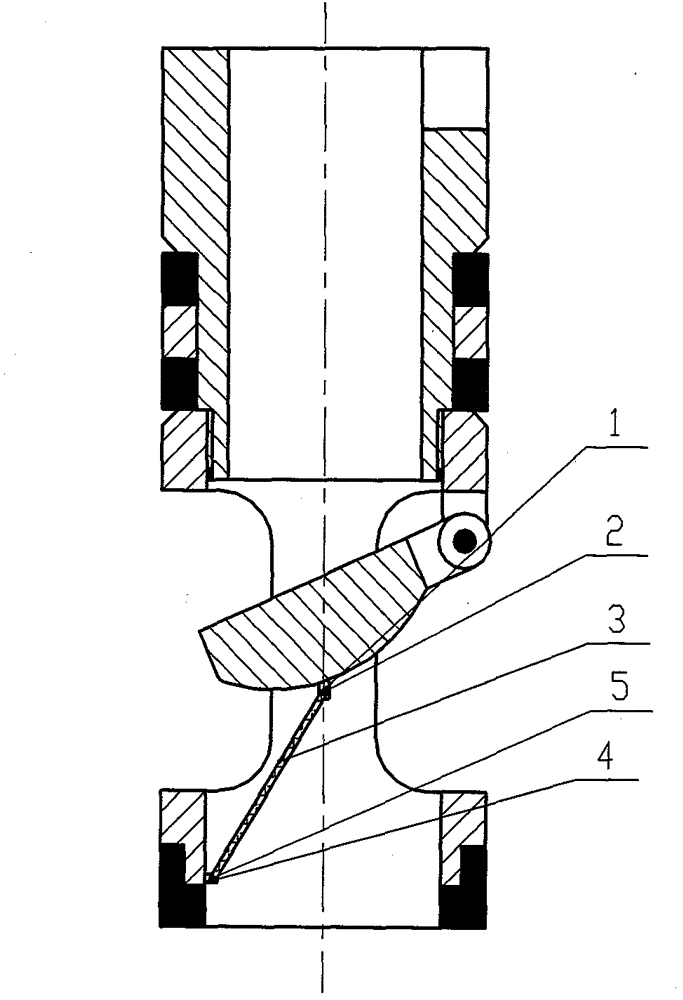
[0013] Such as figure 1 As shown, a pin pull-off type automatic grouting valve float valve is mainly composed of valve cover pin hinge seat 1, pin 2, support rod 3, valve body pin hinge seat 4, and pin 5 on the basis of the valve type float valve. .
[0014] One of support rod 3 is connected with valve cover pin hinge seat 1 with pin 2, and the other end is connected with valve body pin hinge seat 4 with pin 5. The valve is in a half-open state to form a fluid channel to achieve the purpose of automatic grouting. When the pump is turned on and circulated, the support rod 3 is pulled and broken, and the valve is automatically closed under the action of the spring to play the role of a check valve.
Login to View More PUM
 Abstract
The invention discloses a pin-pulled broken-type automatic grouting valve floating valve. The automatic grouting valve floating valve is characterized in that one end of a supporting rod is connected with a valve cover pin hinge seat through a pin, and the other end is connected with a valve body pin hinge seat through another pin. The automatic grouting valve floating valve is simple in structure, and is easy to process, assemble and replace parts. As one end of the supporting rod is connected with the valve cover pin hinge seat through the pin, and the other end is connected with the valve body pin hinge seat through another pin, when a valve of the floating valve is in a half-open state, a fluid channel can be formed to realize the purpose of automatic grouting; and when the supporting rod is pulled and broken in a pumping circulation process, the valve can be automatically closed under the action of a spring to realize a function of a check valve.
Description
Login to View More Claims
Login to View More Application Information
Patent Timeline
 Owner慕武