Al technical title is built by PatSnap Al team. It summarizes the technical point description of the patent document.
A damper, wind speed technology, applied in valve device, valve operation/release device, lift valve, etc., can solve problems such as difficulty in maintaining constant flow of flow valve, inability to preset initial value, and reducing flow growth trend. , to increase wind resistance, reduce wind resistance, improve accuracy and reliability
Inactive Publication Date: 2015-03-11
UNIV OF SHANGHAI FOR SCI & TECH
View PDF4 Cites 0 Cited by
Summary
Abstract
Description
Claims
Application Information
AI Technical Summary
This helps you quickly interpret patents by identifying the three key elements:
Problems solved by technology
Method used
Benefits of technology
Problems solved by technology
[0003] Although the existing purely mechanical air valve devices do not require additional energy consumption, because there is no feedback adjustment mechanism in these air valve devices, they can only reduce the flow rate increase trend, so that the flow rate is roughly reduced, but It is difficult to keep the flow of the flow valve constant, and the air cannot be evenly sent out of the air outlet, and the initial value cannot be preset, the function is very limited, and the control accuracy is not high
Method used
Image
Click on the blue label to locate the original text in one second.
Reading with bidirectional positioning of images and text.
Examples
Embodiment
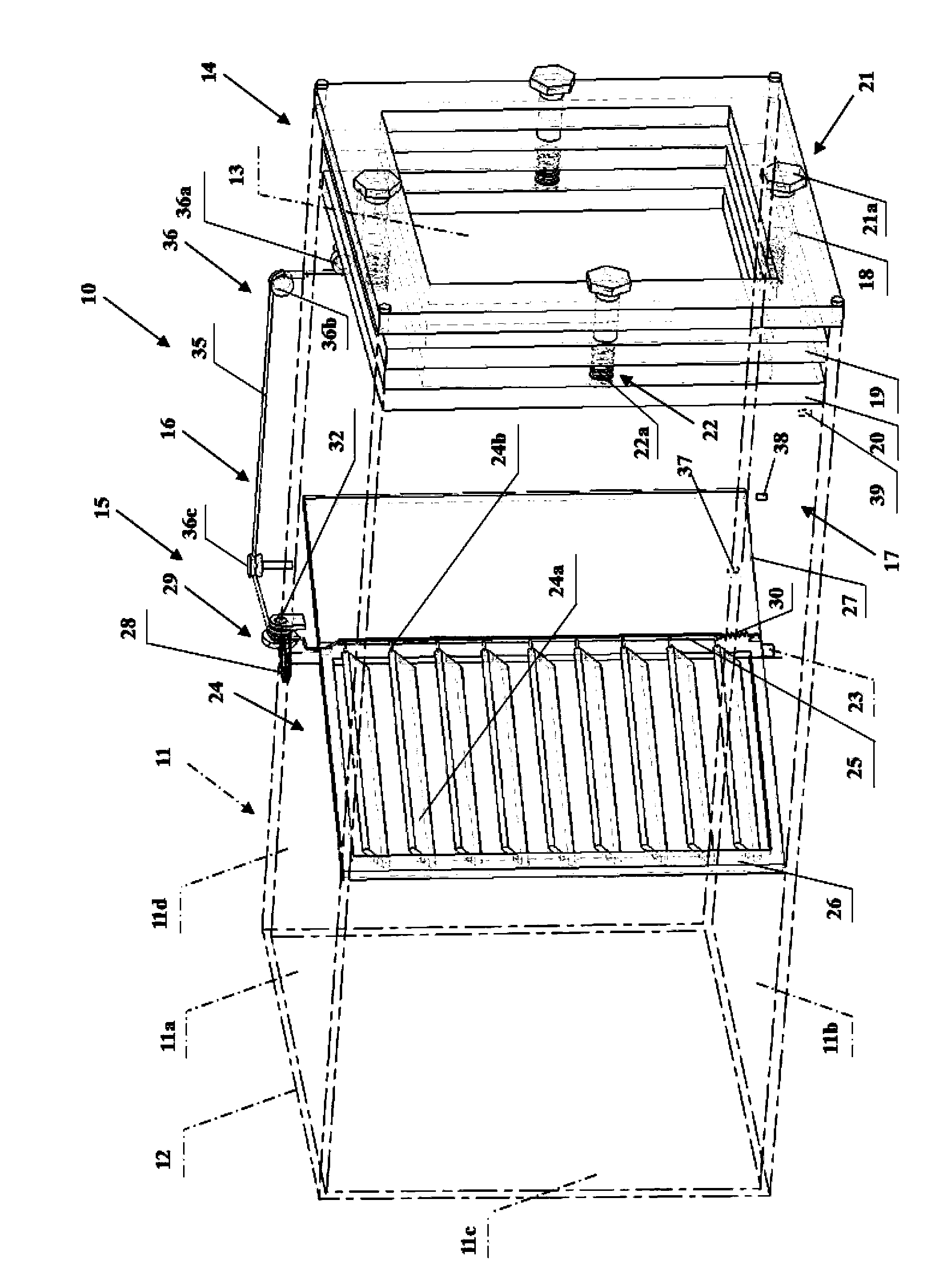
[0021] Fig. 1 is a structural schematic diagram of an embodiment of the damper device involved in the present invention.
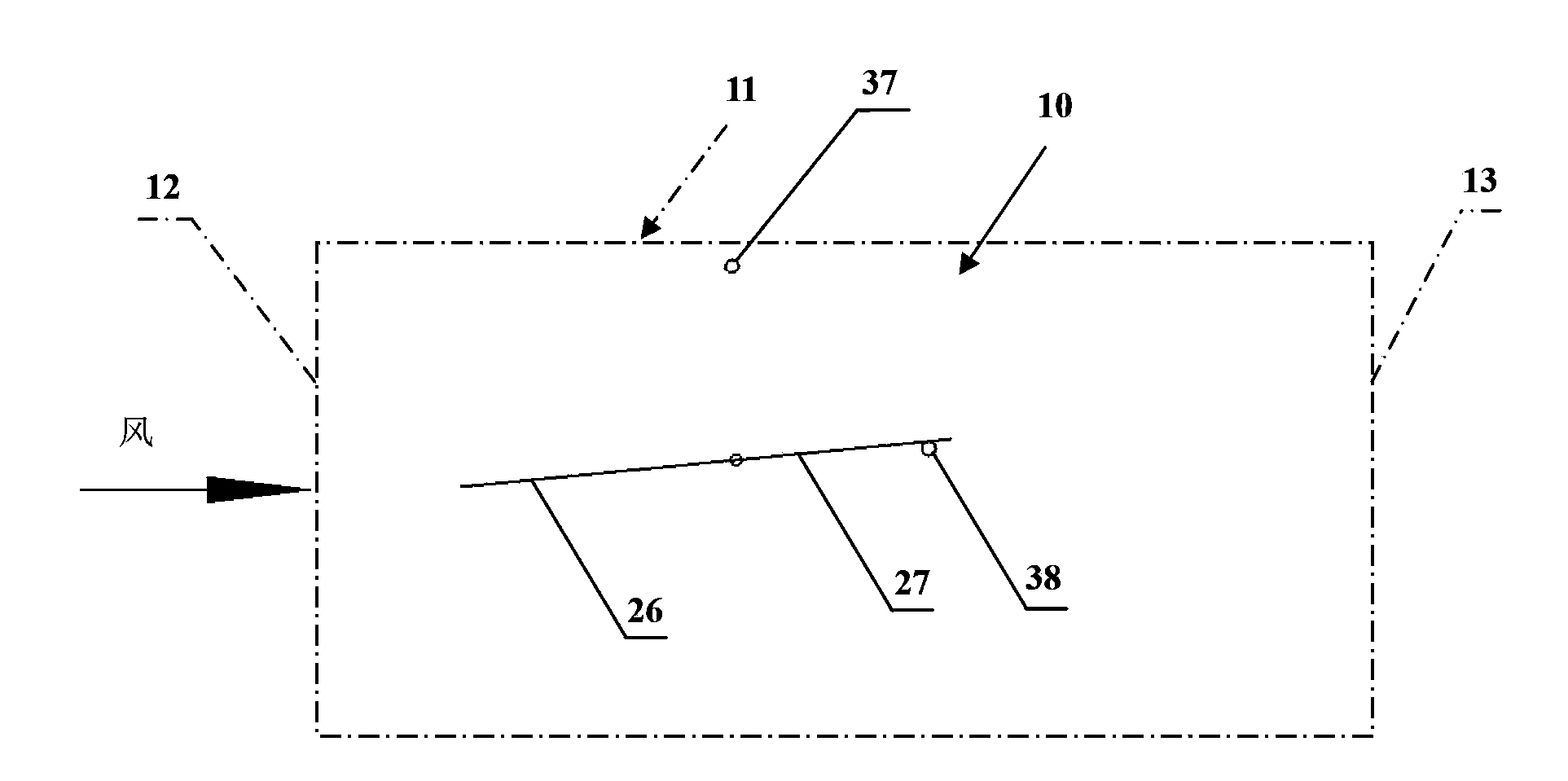
[0022] As shown in Figure 1, the air valve device 10 is installed at the ventilation duct 11 shown in the dotted line in the figure, and is used to adjust the air volume and the wind speed of the wind entering from the air inlet 12 at the front end of the ventilation duct 11, Therefore, the wind speed and air volume of the air sent out from the air outlet 13 at the rear end of the ventilation duct 11 are constant.
[0023] The damper device 10 has a wind receiving part 14 , an adjusting part 15 , a connecting part 16 and a positioning part 17 .
[0024] The ventilation duct 11 includes an upper duct wall 11 a , a duct lower wall 11 b , a duct left wall 11 c and a duct right wall 11 d as shown by dotted lines in the figure.
[0025] In the air valve device 10, the wind receiving part 14 is installed at the air outlet 13, and is used to feel the air volume ...
PUM
Abstract
The invention relates to an air valve device. The air valve device is arranged in a ventilation pipeline, and is used for adjusting the sizes of the air volume and the air speed of the air entering an air inlet which is arranged at the front end of the ventilation pipeline, so the air speed and the air volume of the air delivered from an air delivery port which is arranged at the back end of the ventilation pipeline are constant. The air valve device is characterized in that the air valve device is provided with an air sensing part, an adjusting part, a connecting part and a limiting part, wherein the air sensing part is arranged at the air delivery port, and is used for sensing the air volume and the air speed, the air sensing part comprises a fixing framework, a limiting framework, an air sensing framework, a distance adjusting unit and a thrust component, the adjusting part is arranged at one side, near the air inlet, of the inside of the ventilation pipeline, and is used for adjusting the air volume and the air speed, the adjusting part comprises a first rotary shaft, a plurality of blade components, a blade driving rod, a support framework, an air retaining plate, a rotary gear, an adjusting component and a thrust component, the connecting part is used for connecting the air sensing part with the adjusting part, and comprises a second cable and a steering pulley block, and the limiting part comprises a first limiting table, a second limiting table and a third limiting table.
Description
technical field [0001] The invention relates to a damper device. Background technique [0002] In the air supply outlet of air conditioners and the air supply outlets of some buildings, in order to adjust the wind speed so that the wind can be sent out of the air outlet more evenly, and at the same time to adjust the air volume to a suitable size, so that the wind speed and air volume can be kept constant. Valve device, most of the existing air valve devices are mechatronic devices, which greatly increases energy consumption. [0003] Although the existing purely mechanical air valve devices do not require additional energy consumption, because there is no feedback adjustment mechanism in these air valve devices, they can only reduce the flow rate increase trend, so that the flow rate is roughly reduced, but It is difficult to keep the flow of the flow valve constant, and the air cannot be evenly sent out of the air outlet, and the initial value cannot be preset, the functi...
Claims
Application Information
Patent Timeline
Application Date:The date an application was filed.
Publication Date:The date a patent or application was officially published.
First Publication Date:The earliest publication date of a patent with the same application number.
Issue Date:Publication date of the patent grant document.
PCT Entry Date:The Entry date of PCT National Phase.
Estimated Expiry Date:The statutory expiry date of a patent right according to the Patent Law, and it is the longest term of protection that the patent right can achieve without the termination of the patent right due to other reasons(Term extension factor has been taken into account ).
Invalid Date:Actual expiry date is based on effective date or publication date of legal transaction data of invalid patent.