Collecting main and heat exchanger with same
A technology of collecting tubes and heat exchange tubes is applied in the field of collecting tubes and heat exchangers with collecting tubes, which can solve the problems of high cost of high-frequency welded tubes, and achieve high cost, high reliability and convenient processing. Effect
- Summary
- Abstract
- Description
- Claims
- Application Information
AI Technical Summary
Problems solved by technology
Method used
Image
Examples
Embodiment 1
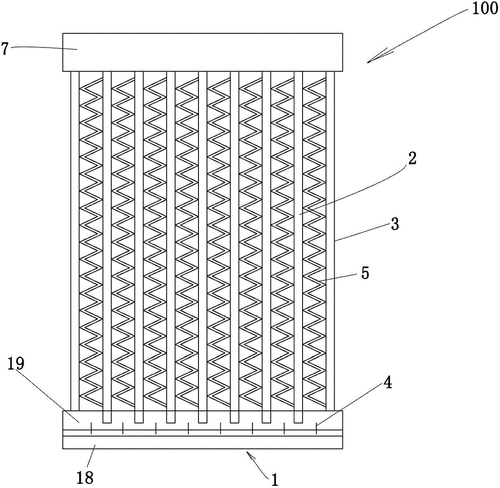
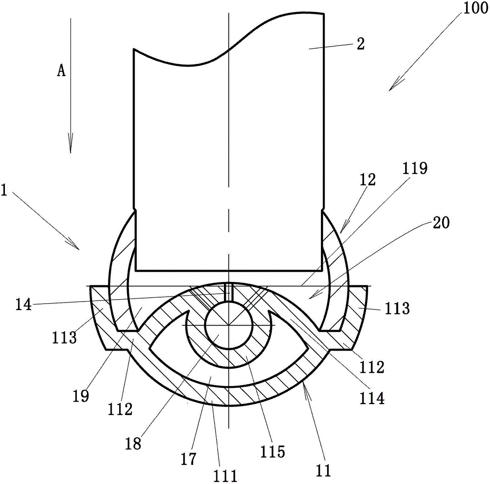
[0039] like figure 1As shown, a heat exchanger 100, such as a microchannel heat exchanger, in accordance with an embodiment of the present invention includes: headers 1, 7 (eg, inlet header 1 and outlet header 7); exchangers such as flat tubes Heat pipes 2 ; fins 5 arranged between the heat exchange pipes 2 ; and side plates 3 . Heat exchangers can be used in HVAC, automotive, refrigeration and transportation fields, and can be used as heat exchangers such as evaporators, condensers and water tanks. The ends of the heat exchange tubes 2 are in fluid communication with the refrigerant distribution cavity 19 of the header. The collector tube 1 has a plurality of openings arranged in the axial direction formed in the tube wall of the collector tube, and the end of the heat exchange tube 2 has steps, for example, in the axial direction of the heat exchange tube 1 In the direction, a step is formed at a predetermined distance from the end face of the end of the heat exchange tube...
Embodiment 2
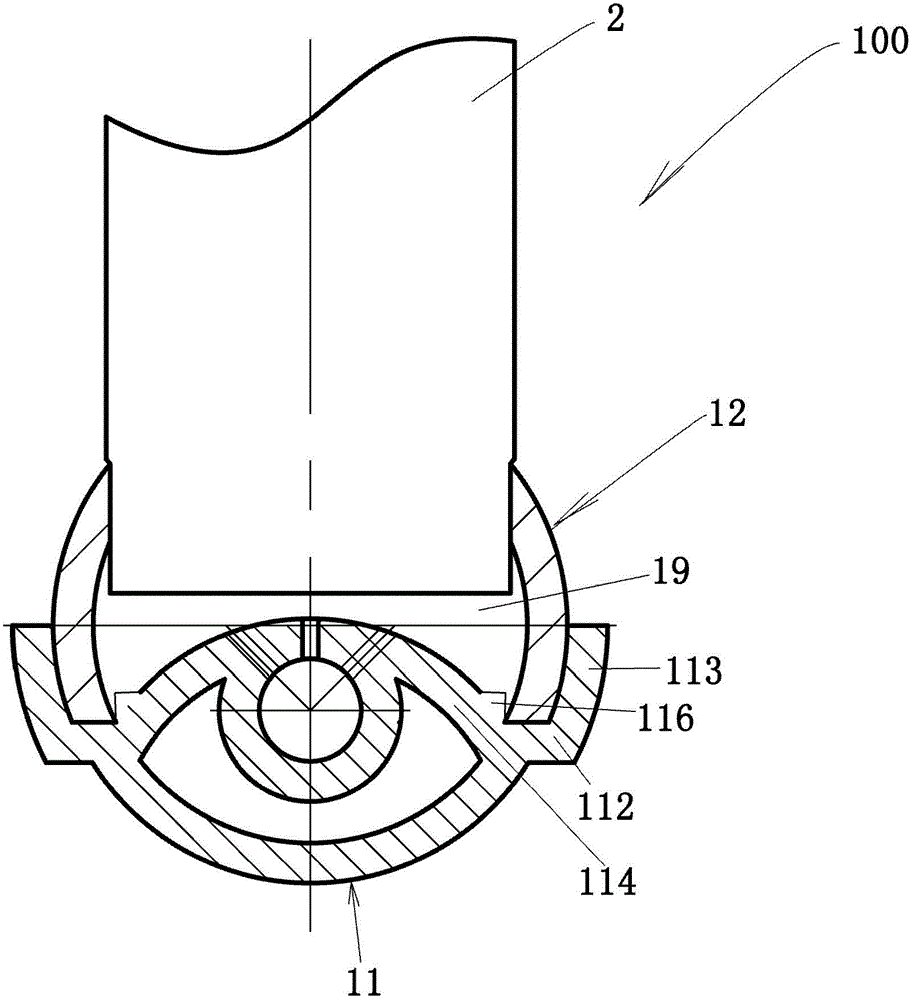
[0055] like image 3 As shown, Embodiment 2 according to the present invention is further improved on the basis of Embodiment 1. Specifically, the first part 11 further includes a protrusion 116, the protrusion 116 is formed on the partition wall part 114, for example, on the surface of the partition wall part 114 facing the refrigerant distribution cavity 19 and is connected with the first part. The two arcuate wall portions 113 are spaced apart by a predetermined distance. The distance may be approximately equal to the thickness of both ends of the arcuate wall portion of the second member 12 , whereby the two ends of the arcuate wall portion of the second member 12 are inserted between the protrusion 116 and the second arcuate wall portion 113 between. By arranging the protrusions 116, the two independent parts 11 and 12 can be ensured to be in good contact and the welding strength can be improved.
Embodiment 3
[0057] like Figure 4 As shown, the plurality of axially extending individual parts 11 , 12 , 13 comprise individual first parts 11 , second parts 12 and third parts 13 , by placing the first part 11 in said assembly direction A , the third part 13 and the second part 12 are placed in sequence and connected together, for example by welding the first part 11 , the third part 13 and the second part 12 together. A refrigerant inlet cavity 18 is formed between the first part 11 and the third part 13 , and a refrigerant distribution cavity 19 is formed between the third part 13 and the second part 12 .
[0058] like Figure 4 shown, when viewed in cross-section, for example at Figure 4 When viewed in the cross-sectional view shown, the first member 11 includes a first arc-shaped wall portion 111 , stepped portions 112 extending outwardly from both ends of the first arc-shaped wall portion 111 , and a stepped portion from the first arc-shaped wall portion 111 . The outer end of ...
PUM
 Abstract
Description
Claims
Application Information
 - R&D
- Intellectual Property
- Life Sciences
- Materials
- Tech Scout
- Unparalleled Data Quality
- Higher Quality Content
- 60% Fewer Hallucinations
Browse by: Latest US Patents, China's latest patents, Technical Efficacy Thesaurus, Application Domain, Technology Topic, Popular Technical Reports.
© 2025 PatSnap. All rights reserved.Legal|Privacy policy|Modern Slavery Act Transparency Statement|Sitemap|About US| Contact US: help@patsnap.com


