
Static electricity atomizing charge-to-mass ratio measuring device

A measuring device, electrostatic spray technology, applied in the direction of measuring device, measuring electrical variables, instruments, etc., to achieve the effect of reducing charge error and accurate measurement

Inactive Publication Date: 2013-06-12
JIANGSU UNIV
View PDF8 Cites 18 Cited by
  • Summary
  • Abstract
  • Description
  • Claims
  • Application Information

AI Technical Summary

Problems solved by technology

In 2006, Chen Zhigang and others studied the measures to improve the accuracy of the charge-to-mass ratio of droplets measured by the mesh target method. The results showed that placing the charge-to-mass ratio in a relatively stable independent space and shielding can obtain a stable signal value; retrieved from the national intellectual property patent Among them, the application number is 201110156068.5, and the patent titled "a real-time measurement system for the charge-mass ratio of wind-sand drifting sand particles" discloses a device for real-time high-frequency measurement of the charge-mass ratio of sand particles, but it is only for the charge-mass ratio of sand particles. The measuring device; the application number is 201010571210.8, and the name is "the device for testing the local charge-to-mass ratio of the atomization space in the electrostatic spray", which mainly discloses the device for testing the local charge-to-mass ratio. The resulting charge error, thereby improving the accuracy of charge-to-mass ratio measurement No technical content has not been disclosed

Method used

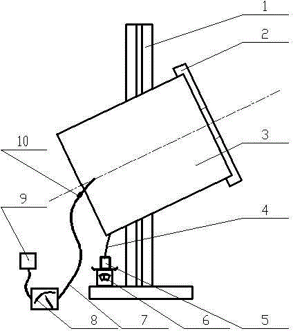
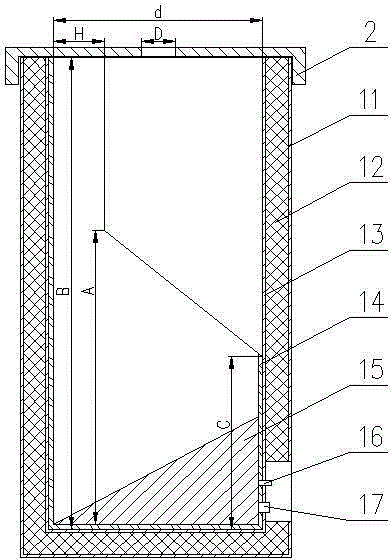
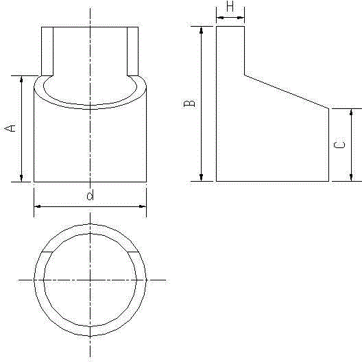

Image

  • Static electricity atomizing charge-to-mass ratio measuring device
  • Static electricity atomizing charge-to-mass ratio measuring device
  • Static electricity atomizing charge-to-mass ratio measuring device

Examples


Embodiment Construction

[0022] In order to better understand the technical solution of the present invention, the present invention will be further described below in conjunction with the accompanying drawings.

[0023] The schematic diagram of the device structure of the present invention is as figure 1 As shown, it is mainly composed of a droplet collection device, a droplet weighing device, a droplet power measurement device, and a data acquisition and processing system. Wherein the droplet carrying device is a liquid collection cylinder 3; the droplet weighing device is a precision electronic balance 6; the droplet power measuring device is a Model 6485 picoammeter 8; the data acquisition and processing system is a PC 9, and the data acquisition software Excelinx and Charge-to-mass ratio analysis software.

[0024] combine figure 1 , when implementing the present invention, according to figure 1 Connect the liquid collection cylinder 3 and the Modle6485 picoammeter 8: connect one end o...


PUM

PropertyMeasurementUnit
Slope angleaaaaaaaaaa
Resistanceaaaaaaaaaa
Wall thicknessaaaaaaaaaa

Abstract

The invention discloses a static electricity atomizing charge-to-mass ratio measuring device which comprises a fogdrop collection device, a fogdrop weighing device, a fogdrop electric quantity measuring device and a data collection and processing system. The fogdrop collection device is a liquid collection cylinder (3) which comprises a liquid collection outer cylinder (11) and a liquid collection inner cylinder (13), and ceramic insulators (12) are arranged in the liquid collection outer cylinder (11) and the liquid collection inner cylinder (13). A graphite inner cylinder (14) is arranged in the liquid collection inner cylinder (13), slope graphite is adopted by the graphite inner cylinder (14), the diameter of the graphite inner cylinder (14) is d, a long bus of the graphite inner cylinder is B, a short bus of the graphite inner cylinder is C, the diameter of an opening of a cylinder cover is D, the distance between a intersecting line of the middle portion cross section and a cylinder bottom is A, the distance between the intersecting line of the middle portion cross section and the long bus is H, and the parameter of he graphite inner cylinder (14) is that A=(0.35-0.45) B; d: A: C =2: 2: 1, B= (13-15)H. A slope cylinder block (15) is arranged in the graphite inner cylinder (14).

Description

technical field [0001] The invention relates to an electrostatic spray charge-to-mass ratio measurement device, in particular to a device for reducing the charge errors caused by the re-measurement and escape of the charged droplets caused by the rebound of the charged droplets after they hit the inner wall of the liquid collection cylinder, and can realize the charge-to-mass ratio measurement device. Electrostatic spray charge-to-mass ratio measurement device for accurate measurement of charge-to-mass ratio of electrospray droplets or particles. Background technique [0002] Researchers at home and abroad have done many studies on the charge-to-mass ratio measurement device, but there is little research on improving the accuracy of the charge-to-mass ratio measurement device. In 2002, A.K.Knight et al. used an array micro-Faraday cylinder to measure the charge-to-mass ratio. Experiments showed that this method not only effectively reduces the detection limit but also im...

Claims


Application Information

Patent Timeline
IPC IPC(8): G01R29/24
Inventor 邱白晶陆洪兰
Owner JIANGSU UNIV
Learn More