Detection method for current converter trigger control device function

A technology of triggering control and detection method, applied in the direction of measuring devices, instruments, measuring electricity, etc., can solve the gaps in the inability to obtain test data, the inability to verify the function of valve-based electronic equipment, the coordination of control and protection equipment, and the verification of reliability functions And other issues

Active Publication Date: 2013-06-12
NR ELECTRIC CO LTD +1
View PDF7 Cites 24 Cited by
  • Summary
  • Abstract
  • Description
  • Claims
  • Application Information

AI Technical Summary

Problems solved by technology

Although some domestic manufacturers have mastered the relevant technologies and can produce products with similar performance, there is still a gap in the functional verification of the work coordination and reliability of the control and protection equipment that is closely related to their cooperation.
Generally, this kind of functional verification can only be carried out at the project site, after all the equipment is installed in place and the test conditions are met, but often due to factors such as tight construction schedules, test conditions or unsatisfactory environments, technicians cannot verify All functions of related equipment such as valve-based electronic equipment and thyristor control and monitoring devices, so that complete test data cannot be obtained, and rich and detailed reference data cannot be provided for other subsequent tests or actual operations.

Method used


Image

  • Detection method for current converter trigger control device function
  • Detection method for current converter trigger control device function
  • Detection method for current converter trigger control device function

Examples


Embodiment Construction

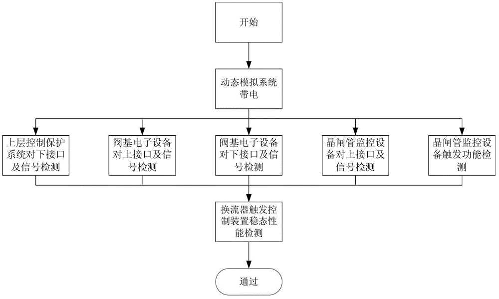
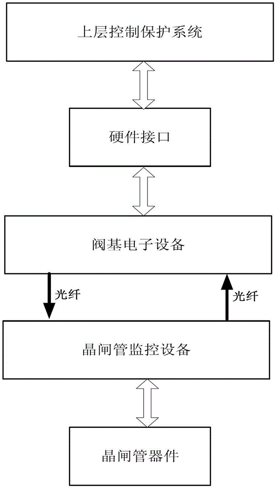
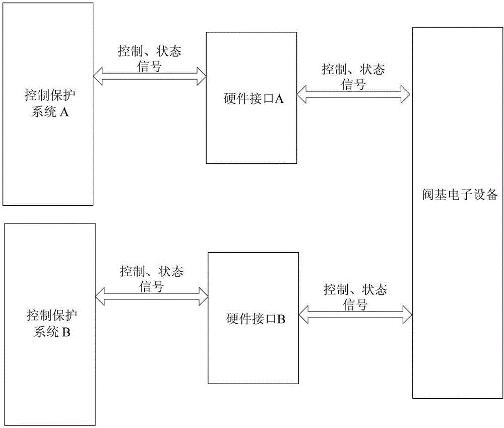
[0032] The technical solutions of the present invention will be described in detail below in conjunction with the accompanying drawings.

[0033] The invention provides a method for detecting the function of a converter trigger control device. Firstly, it is necessary to establish a dynamic simulation test system integrating primary and secondary. Thyristor equipment, thyristor monitoring equipment, voltage regulators, voltage acquisition devices, power load equipment, and physical connection cables between the equipment in each link. The physical connection cables mainly include cables and optical cables; the test system circuit is as follows: Figure 4 As shown, the primary side of the voltage regulating device is connected to the power supply by a cable, and the secondary side is connected to the three-phase input terminal of the thyristor device of the converter valve by a cable; the output terminal of the thyristor device of the converter valve is connected to the power lo...


PUM


Abstract

The invention discloses a detection method for a current converter trigger control device function. The detection method comprises the following steps of: firstly, establishing a secondary integration dynamic simulation test system; detecting the validity of an interface logic function between an upper-layer control protection system and valve base electronic equipment; detecting the validity of an interface logic function between the valve base electronic equipment and thyristor monitoring equipment; detecting the validity of the trigger function and the protecting and monitoring function of the thyristor monitoring equipment; and simulating a test method that the thyristor is continuously triggered to be conducted in a commutation time sequence on the upper-layer control protection system to detect the validity of the function of the whole current converter trigger control device in a long-time continuous operation mode. With the method, before engineering projects, such as high-voltage direct-current power transmission, static high-voltage dynamic reactive compensation and direct-current ice melting are implemented or in the process that the relevant test researches are carried out, the working performance of the valve base electronic equipment is effectively tested, and the condition that whether the cooperation of the valve base electronic equipment and the control protection equipment under various working conditions satisfies the system design requirement is effectively tested.

Description

technical field [0001] The invention belongs to the field of high-power electric power electronics, in particular to a method for detecting the function of a converter trigger control device. Background technique [0002] The converter trigger control device includes the upper control and protection system, valve base electronic equipment, thyristor monitoring equipment and physical connection cables between the equipment in each link, and is used as a project for high-voltage direct current transmission, static high-voltage dynamic reactive power compensation and direct current ice melting. The core secondary equipment in the converter valve is mainly used for trigger logic processing of the converter valve, controlling the conduction of the thyristor, monitoring the operation status of the thyristor and its related equipment, and protecting the thyristor from the influence of the valve stress, so as to ensure the trigger control device of the converter. Safe and reliable c...

Claims


Application Information

Patent Timeline
Patent Type & Authority Applications(China)
IPC IPC(8): G01R31/00G05B23/02
Inventor 高晟辅冯鸫董云龙刘海彬李海英国建宝
Owner NR ELECTRIC CO LTD
Why Eureka
Try Eureka