A method for displaying physical objects in video with network function

A technology of physical display and network function, applied in the direction of electrically operated teaching aids, instruments, educational appliances, etc., can solve the problems of inconvenient operation, small working surface of the laser pointer, image afterimage, etc., to increase the connection distance, connection distance and method. Flexibility and convenience, the effect of increasing ease of operation

Inactive Publication Date: 2016-03-09
杭州华银教育多媒体科技股份有限公司
View PDF5 Cites 0 Cited by
  • Summary
  • Abstract
  • Description
  • Claims
  • Application Information

AI Technical Summary

Problems solved by technology

[0004] The first implementation is that the operator directly points on the real object. However, such an operation can easily cause image afterimages on the projection screen, so that the position corresponding to the operator’s pointing on the real object image on the projection screen appears a black area. ;
[0005] The second way of realization is that the operator uses a laser pointer to directly point to the corresponding position of the physical image on the projection screen. However, this method has a poor pointing effect. Its position cannot be highlighted on the projection surface, and the operator often needs to shake the laser pointer back and forth;
[0006] The third implementation method is to connect the display stand to the PC with a Usb, and the operator uses the PC to control the application software related function buttons of the video booth to make annotations. This is also the most practical and advanced processing method so far, but In the actual application process, this method is increasingly unable to satisfy the rich and colorful teaching process.
The biggest disadvantage is that teachers can only operate in a fixed place in the classroom, and cannot interact with students face to face
In addition, the Usb connection needs to consider the distance between the PC and the video booth, and the flexibility is not high
[0007] It can be seen that when the existing video real object display stand requires the operator to give key instructions on the specific position of the real object image on the projection screen, problems such as inconvenient operation, limitation of the teaching place, distance between the PC and the display stand, etc. are prone to occur.

Method used


Image

  • A method for displaying physical objects in video with network function
  • A method for displaying physical objects in video with network function

Examples


Embodiment 1

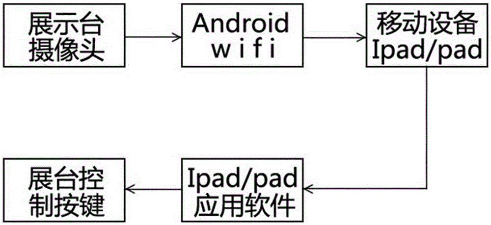
[0047] In an embodiment, the communication process between the video physical display platform and the mobile device terminal Ipad or Pad is as follows: figure 1 shown. Among them, the data generation module of the camera of the video physical display stand collects the teaching material screen of the display stand base, generates a video stream suitable for network transmission, and transmits the video stream to the mobile device installed with the data receiving module through the wireless Wi-Fi function of the Android system On a terminal such as an Ipad or an Android pad, after the Ipad or pad installed with a data receiving module is connected to the real video display stand, it receives the video stream transmitted by the real video display stand and displays it in real time. Users can annotate and modify the current video screen through the human-computer interaction module and command sending module on the Ipad or pad, and control the control buttons and other function...

Embodiment 2

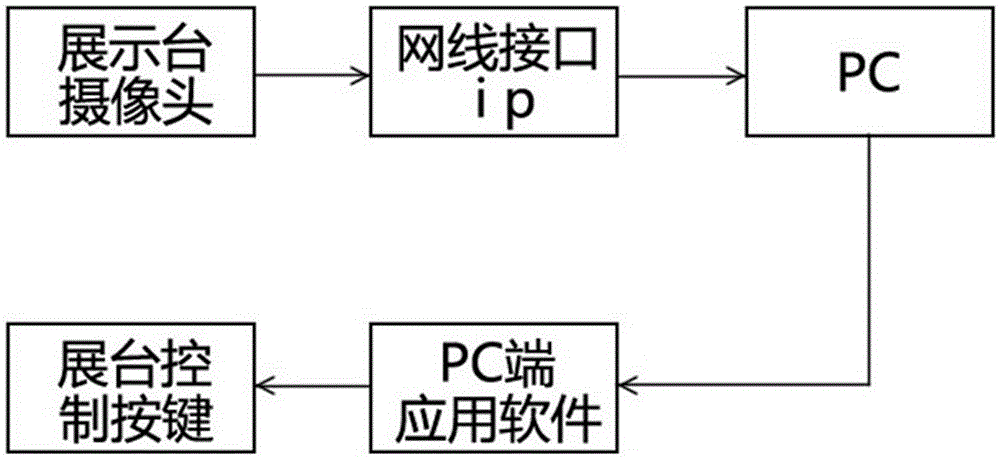
[0049] In the embodiment, the communication process between the video physical display platform and the PC terminal is as follows: figure 2 shown. Among them, the data generation module of the camera of the real video display stand collects the teaching material picture of the base of the display stand, generates a video stream suitable for network transmission, transmits it to the PC end with a data receiving module through the network cable interface, and receives the data transmitted by the real video display stand Video streams and implements display to monitor output. The human-computer interaction module and instruction sending module on the PC side include annotations and modifications to the video stream screen, control buttons for the physical video display stand, and other related function buttons, all of which communicate through TCP and signaling. Compared with the traditional USB connection, it has the advantages of fast effect, good signal and long transmission...


PUM


Abstract

The invention provides a video real object displaying system with a network function. The video real object displaying system comprises a video real object displaying platform, a PC (Personal Computer) terminal and / or a mobile equipment terminal, wherein wireless communication modules are respectively arranged in the video real object displaying platform and the mobile equipment terminal; the video real object displaying platform comprises a camera and a VGA (Video Graphics Array) interface and is internally provided with an Android operation system; a data transmission module and an instruction control module are arranged in the operation system; the camera also comprises a data generation module; and the PC terminal and / or the mobile equipment terminal comprises a data receiving module, an instruction transmitting module and a human-machine interaction module. The invention also provides a video real object displaying method. The video real object displaying platform can be used for transmitting video streams acquired by the camera to the mobile equipment terminal in a wireless manner; and the terminal receives video stream data of the video real object displaying platform and displaying in real time and outputting the video stream data, can execute operations such as commentation and modification on a video frame and can also remotely control functional keys of the displaying platform. A teacher giving lessons can hold the terminal with hand for teaching, so that the problem that lessons can be only given at fixed places is solved.

Description

technical field [0001] The invention relates to the field of multimedia equipment, more specifically, to a video object display system with network functions. Background technique [0002] The video physical display stand is one of the indispensable teaching equipment in the multimedia classroom. It can be used in various information technology teaching. When it is connected to a projector or a TV, it can display materials, handouts, objects, slides, etc. clearly. displayed. [0003] The usual video display stand includes several parts: camera, light source, table and PC-side control software. Place books, documents, real objects and other objects on the table of the display stand, and after aiming the camera above the table at the object, the real object will be output on the projection surface (for example: display device). When applying the software of the video real object display platform on the PC side, sometimes the operator needs to give key instructions to the spe...

Claims


Application Information

Patent Timeline
Patent Type & Authority Patents(China)
IPC IPC(8): G09B5/02
Inventor 刘波周永军陈吉庆钱栩磊
Owner 杭州华银教育多媒体科技股份有限公司
Why Eureka
Try Eureka