
Microgrid power supply system and control method thereof

A technology of power supply system and micro-grid, applied in sustainable manufacturing/processing, AC network load balancing, single-network parallel feeding arrangement, etc. The effect of reducing battery capacity

Inactive Publication Date: 2013-06-12
DALIAN GREAT OCEAN NEW ENERGY DEV
View PDF5 Cites 11 Cited by
  • Summary
  • Abstract
  • Description
  • Claims
  • Application Information

AI Technical Summary

Problems solved by technology

[0002] At present, energy conservation and emission reduction have become the focus of social attention. Among them, solar energy and wind energy are more and more widely used due to their abundant resources, cleanness, and wide distribution. The power supply systems using solar energy and wind energy in the prior art exist as follows Problem: 1. It does not cover AC power from solar thermal power generation system, wind power generation system, diesel engine power generation system and gas Stirling power generation system to solve the problem of off-grid and grid-connected supply; 2. When using solar Stirling When the energy input to the Stirling engine increases, if the increased energy cannot be successfully converted into electrical energy and sent to the grid, the speed of the Stirling engine will rise rapidly, causing the system to generate electricity The frequency is unstable; 3. All the power generated by the AC power generation system is converted into DC power by the rectifier and stored in the battery, which leads to a large demand for the capacity of the battery in the power supply system, which increases the system cost; 4. The frequency of the power supply of the AC power generation system Need to be controlled; 5. Using AC-DC-AC conversion reduces system efficiency; 6. The existing power supply system controls the charging and discharging process of the battery is complicated

Method used


Image

  • Microgrid power supply system and control method thereof
  • Microgrid power supply system and control method thereof

Examples


Embodiment Construction

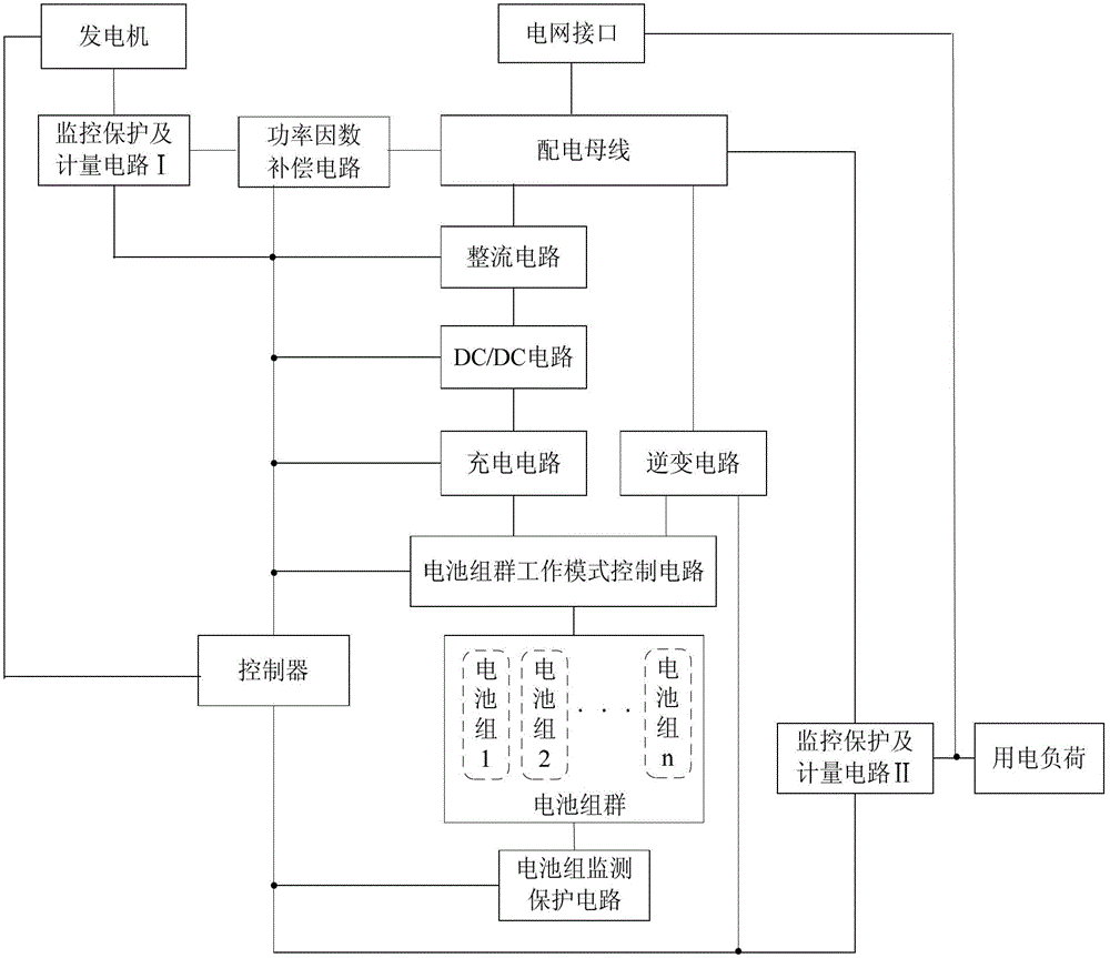
[0037] like figure 1 A micro-grid power supply system is shown, including: a generator; a rectifier circuit connected to the generator through a power distribution bus for converting the output alternating current of the generator into direct current; Converted DC / DC circuit; connect the DC / DC circuit and connect the battery group through the battery group working mode control circuit, and use the DC / DC circuit to output direct current to charge the battery pack working in the charging mode; connect The controller and the battery group are used to set the battery group working mode control circuit of the battery group working mode according to the power state of the battery group; the battery group working mode includes charging mode, power supply mode and standby mode; and the battery group A battery group with at least three battery packs connected to the working mode control circuit; the battery group is connected through the battery group working mode control circuit, and ...


PUM


Abstract

The invention discloses a microgrid power supply system and a control method thereof. The system comprises a generator, a rectification circuit, a DC (Direct Current) / DC circuit, a charging circuit, a battery pack working mode control circuit, a battery pack, an inversion circuit, a power distribution bus bar and a controller and further comprises a monitoring protection and metering circuit I, a monitoring protection and metering circuit II, a power factor compensation circuit and a battery pack monitoring protection circuit. The microgrid power supply system can work in a grid-connected state, also can realize off-grid power supply, and can be used for effectively combining a solar generator, a stand-by generator and a battery pack to realize reliable and continuous power supply.

Description

technical field [0001] The invention relates to a microgrid power supply system and a control method. Background technique [0002] At present, energy conservation and emission reduction have become the focus of social attention. Among them, solar energy and wind energy are more and more widely used due to their abundant resources, cleanness, and wide distribution. The power supply systems using solar energy and wind energy in the prior art exist as follows Problem: 1. It does not cover AC power from solar thermal power generation system, wind power generation system, diesel engine power generation system and gas Stirling power generation system to solve the problem of off-grid and grid-connected supply; 2. When using solar Stirling When the energy input to the Stirling engine increases, if the increased energy cannot be smoothly converted into electrical energy and sent to the grid, the speed of the Stirling engine will rise rapidly, causing the system to generate electrici...

Claims


Application Information

Patent Timeline
IPC IPC(8): H02J3/38H02J3/32
CPCY02E70/30Y02P80/14
Inventor 张彦明王振声
Owner DALIAN GREAT OCEAN NEW ENERGY DEV
Learn More