
Motor driving device without sensor, and back electromotive force detection circuit and detection method

一种反电动势、检测电路的技术,应用在电子换向电动机控制、单个电动机转速/转矩控制、电气元件等方向,能够解决成本增高、降低产品竞争力等问题,达到降低成本需求的效果

Active Publication Date: 2013-06-12
SYST GEN
View PDF5 Cites 3 Cited by
  • Summary
  • Abstract
  • Description
  • Claims
  • Application Information

AI Technical Summary

Problems solved by technology

That is to say, the cost of installing a sensorless motor drive device will increase accordingly, which relatively reduces the competitiveness of the product

Method used


Image

  • Motor driving device without sensor, and back electromotive force detection circuit and detection method
  • Motor driving device without sensor, and back electromotive force detection circuit and detection method
  • Motor driving device without sensor, and back electromotive force detection circuit and detection method

Examples


Embodiment Construction

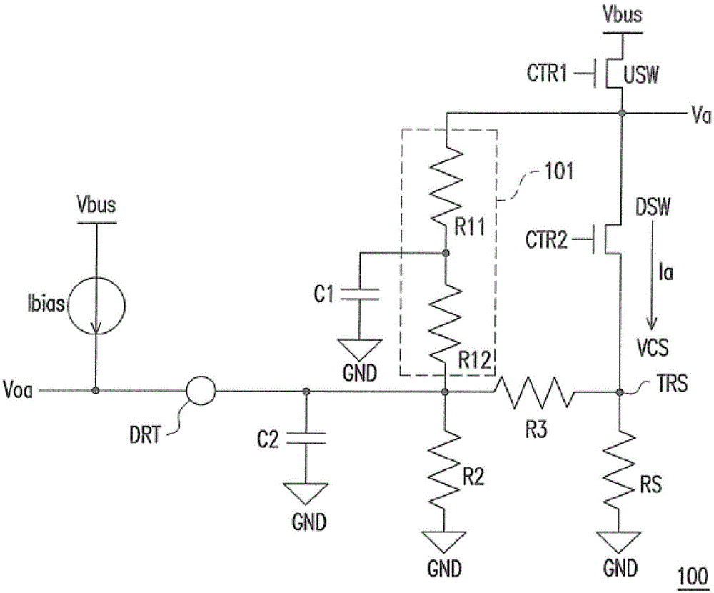
[0039] Please refer to figure 1 , figure 1 A schematic diagram of a back electromotive force detection circuit 100 of a motor according to an embodiment of the present invention is shown. The back EMF detection circuit 100 includes an upper switch USW, a lower switch DSW, a current detection resistor RS, an impedance generator 101, R2 and R3, a bias current source Ibias, and filter capacitors C1 and C2. The first end of the upper switch USW is coupled to the reference voltage source Vbus, and the second end thereof is coupled to the driving voltage Va, and is controlled by the control signal CTR1. The first terminal of the lower switch DSW is coupled to the second terminal of the upper switch USW, and the lower switch DSW is controlled by the control signal CTR2. The current detection resistor RS is connected in series between the second end of the lower switch DSW and the reference ground voltage GND. A first terminal of the impedance generator 101 is coupled to a second t...


PUM


Abstract

The invention provides a motor driving device without a sensor, and a back electromotive force detection circuit and a detection method. The motor driving device comprises an upper end switch, a lower end switch, a current detection resistor, a first impedance generator, a second impedance generator and a third impedance generator. The upper end switch is controlled by a first control signal, and the lower end switch is controlled by a second control signal. The current detection resistor is in series connection between a second end of the lower end switch and a reference grounding voltage. A first end of the first impedance generator is coupled to the upper end switch and a second end of the first impedance generator generates a back electromotive force detection result. The second impedance generator is in series connection between the first impedance generator and the reference grounding voltage. The third impedance generator is in series connection between the lower end switch and a coupling point of the firstimpedance generator and the second impedance generator. Impedance of the first impedance generator, the second impedance generator and the third impedance generator is determined based on at least one characteristic parameter of a motor.

Description

technical field [0001] The present invention relates to a sensorless motor drive device, and in particular to a sensorless motor drive device, a counter electromotive force detection circuit and a detection method. Background technique [0002] In the conventional technical field, in order to complete the installation of a sensorless motor drive device, it is an important task to estimate the state of the rotor of the motor. It is a very common practice to convert the sensing signal of the virtual motor rotor through the back electromotive force of the motor. [0003] In the existing technical field, the sensing signal of the virtual motor rotor is obtained by using parameters in the motor to cooperate with multiple electrical and mechanical characteristics of the motor during operation. In this calculation method, in addition to matching a look-up table (LUT) of a certain size, a lot of complicated calculations are required to complete. In order to cope with such calculat...

Claims


Application Information

Patent Timeline
Patent Type & Authority Applications(China)
IPC IPC(8): H02P6/18H02P6/08
CPCH02P6/182H02P6/085
Inventor 林奕圻尹治平杨世仁
Owner SYST GEN
Learn More