Lamp
A lamp head and main reflector technology, applied in the field of lamps, can solve problems such as temperature rise, increase in heat load of circuit units, reduction in heat dissipation characteristics/heat transfer characteristics, etc., to achieve the effect of reducing occlusion
- Summary
- Abstract
- Description
- Claims
- Application Information
AI Technical Summary
Problems solved by technology
Method used
Image


Examples
no. 1 approach
[0050] A first embodiment for carrying out the present invention will be described in detail with reference to the drawings.
[0051] 1. Overall structure
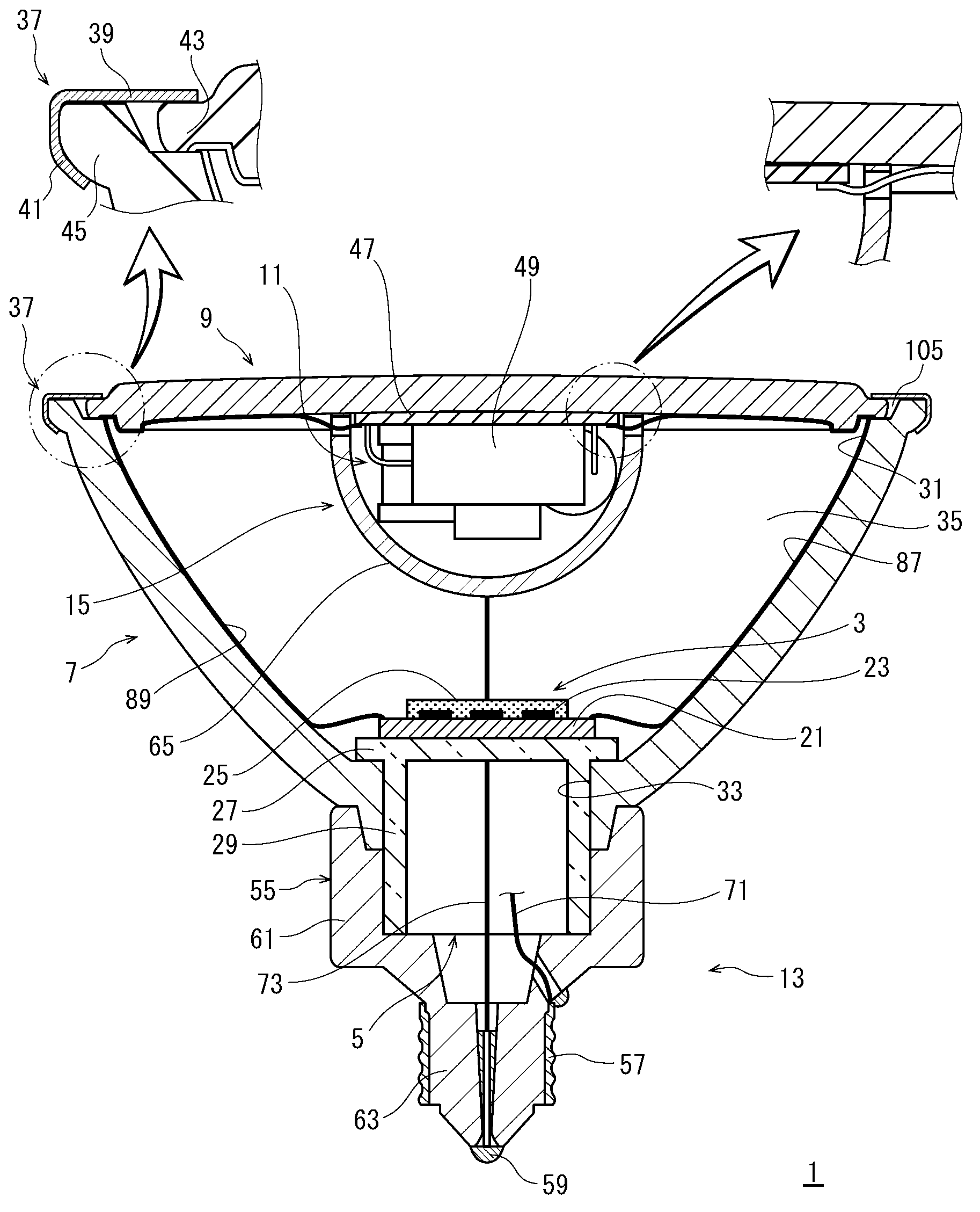
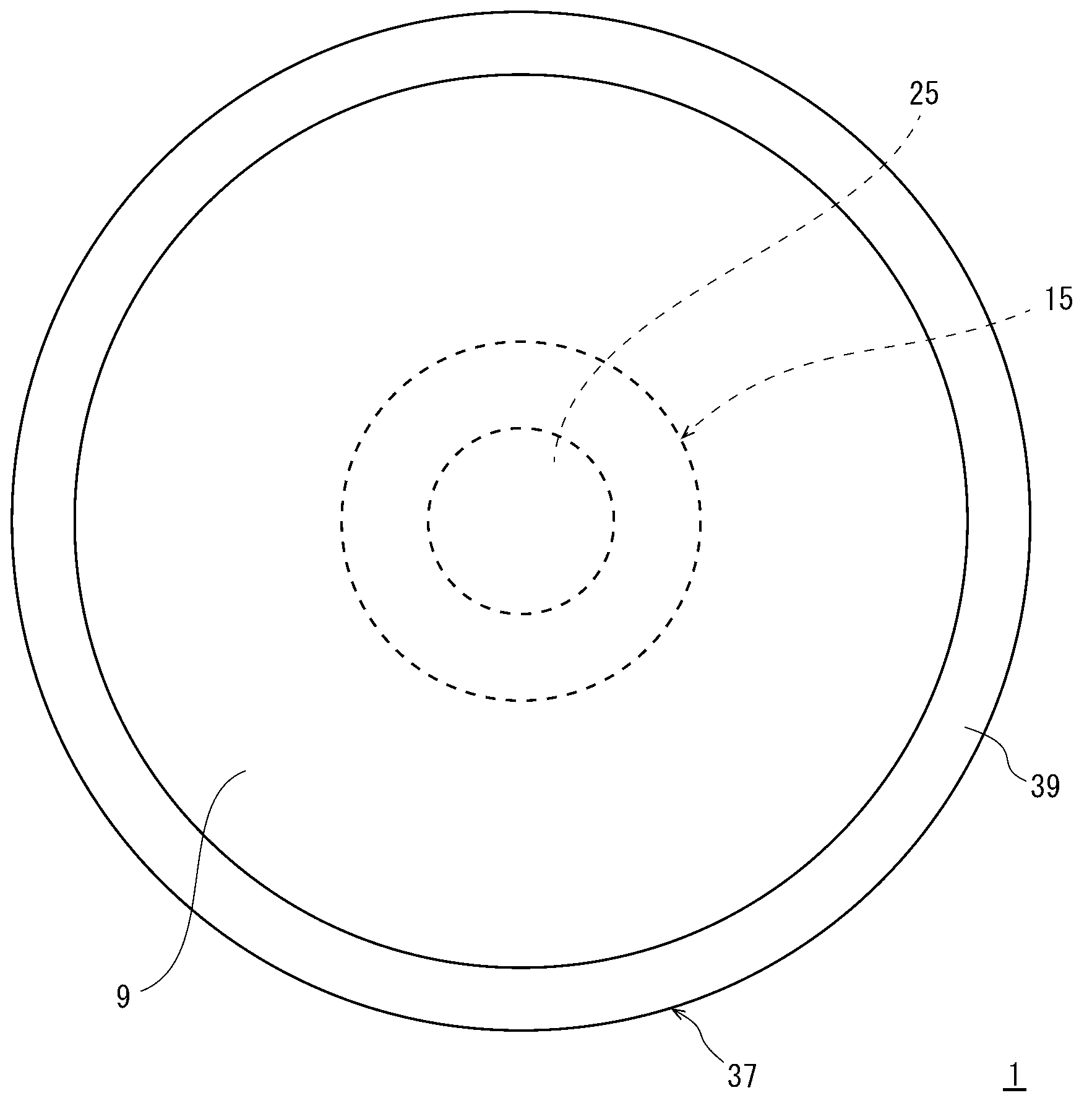
[0052] figure 1 It is a sectional view showing the structure of the LED lamp 1 of the first embodiment, figure 2 It is a plan view of the LED lamp 1 viewed from the side opposite to the base 13 .
[0053]An LED lamp (corresponding to the "lamp" of the present invention) 1 includes an LED module 3 having an LED (light emitting diode) as a light emitting body, a lamp holder 5 on which the LED module 3 is mounted, and the LED module 3 is stored inside via the lamp holder 5 The main reflector 7, the front panel 9 arranged at one end of the main reflector 7, the circuit unit 11 for making the LED emit light, and the lamp holder 13 electrically connected with the circuit unit 11, the circuit unit 11 is covered by the circuit case 15.
[0054] That is, the LED lamp 1 has: a main reflector 7 having an opening 31 at one end and...
no. 2 approach
[0114] In the first embodiment, there is no light concentrating mechanism for concentrating the light emitted from the LED module 3 on the circuit case 15 arranged in front of the LED module 3 (in the direction of light emission), so that the light emitted from the LED module 3 The light is efficiently reflected by the sub-reflecting surface 65 of the circuit case 15 toward the main reflector 7. In the second embodiment, a mode in which a reflector is used as a light-condensing mechanism will be described. In addition, about the same part as the structure demonstrated in 1st Embodiment, the same code|symbol as 1st Embodiment is used.
Embodiment approach 1
[0116] Figure 4 It is a sectional view showing the structure of the LED lamp 201 of the second embodiment 1. FIG.
[0117] The LED lamp 201 of the second embodiment 1 has an LED module 3, a lamp holder 5, a main reflector 7, a front panel 9, a circuit unit 11, a lamp base 13, and a circuit case 15, and is provided with a lamp for emitting light from the LED module 3. The reflector 203 that reflects light toward the circuit case 15 side. In addition, the surface on the side of the LED module 3 in the circuit case 15 becomes the sub-reflective surface 65 .
[0118] Here, the reflector 203 is formed in a cylindrical shape surrounding the sealing body 25 of the LED module 3 . The cylindrical reflector 203 is mounted on the mounting board 21 of the LED module 3 so that the center of the light emitting part of the LED module 3 is located on the central axis.
[0119] The diameter of the reflector 203 increases along the central axis of the reflector 203 (also the optical axis of...
PUM
 Abstract
Description
Claims
Application Information
 - R&D
- Intellectual Property
- Life Sciences
- Materials
- Tech Scout
- Unparalleled Data Quality
- Higher Quality Content
- 60% Fewer Hallucinations
Browse by: Latest US Patents, China's latest patents, Technical Efficacy Thesaurus, Application Domain, Technology Topic, Popular Technical Reports.
© 2025 PatSnap. All rights reserved.Legal|Privacy policy|Modern Slavery Act Transparency Statement|Sitemap|About US| Contact US: help@patsnap.com