
Abrasive belt automatic feeding mechanism

An automatic feeding and abrasive belt technology, applied in abrasive belt grinders, grinding drives, grinding machine parts, etc., can solve the problems of difficult operation, large waste, unstable feed rate, etc. The effect of stable quantity, reasonable structure and convenient operation

Active Publication Date: 2017-07-28
潍坊天润曲轴有限公司
View PDF5 Cites 0 Cited by
  • Summary
  • Abstract
  • Description
  • Claims
  • Application Information

AI Technical Summary

Problems solved by technology

[0002] At present, the polishing of the crankshaft journal adopts abrasive belt polishing, and the abrasive belt polishing machine has a flaw in the design of the abrasive belt feed control. The feeding of the abrasive belt polishing machine is manually fed, which is difficult to operate, the feed is unstable, and the waste is large.

Method used


Image

  • Abrasive belt automatic feeding mechanism
  • Abrasive belt automatic feeding mechanism
  • Abrasive belt automatic feeding mechanism

Examples


Embodiment 1

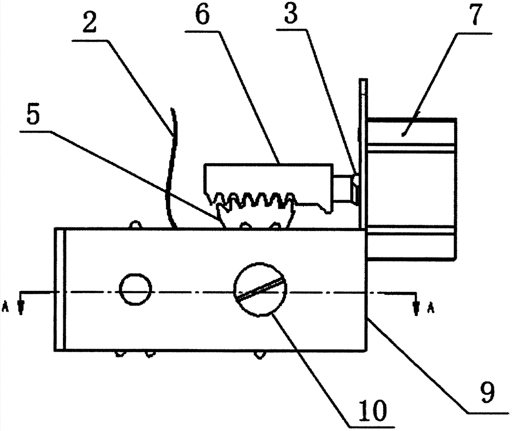
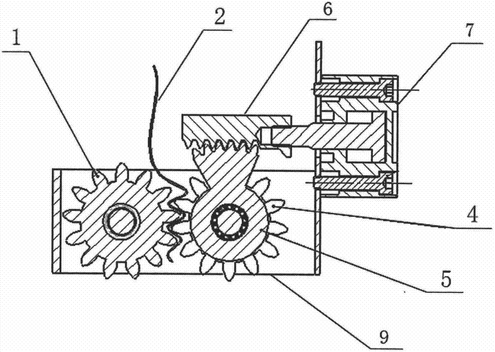
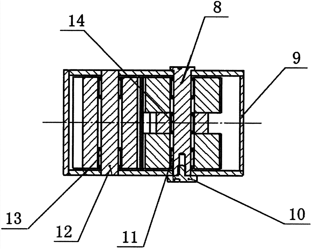
[0017] Such as Figure 1~3 Shown, a kind of abrasive belt automatic feeding mechanism comprises feeding cylinder 7, feeding rack 6, tape cassette 9, and long gear 1, two short gears 4, feed Sector gear 5, fixed shaft 12 and feed shaft 8, fixed shaft 12 passes through the long gear 1 that one-way needle roller bearing II13 is installed at both ends and is fixed on the tape cassette 9 front ends, and feed shaft 8 passes through the single The short gear 4 of the needle roller bearing I11, the feed sector gear 5 with the one-way needle roller bearing III14 and another short gear 4 with the one-way needle roller bearing I11 installed are installed in the middle part of the tape cassette 9, two The short gear 4 meshes with the long gear 1 at the same time, and the two ends of the feed shaft 8 are installed in the symmetrical mounting holes on both sides of the tape cassette 9; the feed cylinder 7 is fixed on the outside of the rear end of the tape cassette 9, and the feed gear The...

Embodiment 2

[0021] Such as Figure 1~3 Shown, a kind of abrasive belt automatic feeding mechanism comprises feeding cylinder 7, feeding rack 6, tape cassette 9, and long gear 1, two short gears 4, feed Sector gear 5, fixed shaft 12 and feed shaft 8, fixed shaft 12 passes through the long gear 1 that one-way needle roller bearing II13 is installed at both ends and is fixed on the tape cassette 9 front ends, and feed shaft 8 passes through the single The short gear 4 of the needle roller bearing I11, the feed sector gear 5 with the one-way needle roller bearing III14 and another short gear 4 with the one-way needle roller bearing I11 installed are installed in the middle part of the tape cassette 9, two The short gear 4 meshes with the long gear 1 at the same time, and the two ends of the feed shaft 8 are installed in the symmetrical mounting holes on both sides of the tape cassette 9; the feed cylinder 7 is fixed on the outside of the rear end of the tape cassette 9, and the feed gear The...


PUM


Abstract

The invention discloses a sanding belt automatic feeding mechanism comprising a feeding air cylinder, a feeding rack, a winding box, a long wheel gear, two short wheel gears, a feeding fan-shaped wheel gear, a fixed shaft and a feeding shaft, wherein the long wheel gear, the two short wheel gears, the feeding fan-shaped wheel gear, the fixed shaft and the feeding shaft are all located inside the winding box. The fixed shaft penetrates through the long wheel gear and is fixed at the front end of the winding box, wherein unidirectional needle bearings II are installed at two ends of the long wheel gear. The feeding shaft sequentially penetrates through one of the short wheel gears, the feeding fan-shaped wheel gear and the other short wheel gear and is installed at the middle portion of the winding box, wherein a unidirectional needle bearing I is installed on one of the short wheel gears, a unidirectional needle bearing III is installed on the feeding fan-shaped wheel gear and a unidirectional needle bearing I is installed on the other short wheel gear. The two short wheel gears are meshed with the long wheel gear simultaneously. The air cylinder is fixed on the outer side of the rear end of the winding box. The feeding rack is installed at the front end of the feeding air cylinder, located above the winding box and meshed with the feeding fan-shaped wheel gear. According to the sanding belt automatic feeding mechanism, not only manual feeding but also automatic feeding can be achieved. The sanding belt automatic feeding mechanism has the advantages of being convenient to operate, stable in feeding rate, reasonable in structure and easy to manufacture.

Description

technical field [0001] The invention relates to a feeding mechanism, in particular to an automatic feeding mechanism for abrasive belts. Background technique [0002] At present, the polishing of the crankshaft journal adopts abrasive belt polishing. The abrasive belt polishing machine has a flaw in the design of the abrasive belt feed control. The feeding of the abrasive belt polishing machine is manually fed, which is difficult to operate, the feed is unstable, and the waste is large. Contents of the invention [0003] The technical problem to be solved by the present invention is to overcome the deficiencies of the above-mentioned prior art, and provide an abrasive belt feeder with reasonable structure, simple manufacture, convenient operation, stable feed rate, which can realize both manual feed and automatic feed. mechanism. [0004] The abrasive belt automatic feeding mechanism of the present invention comprises a feeding cylinder, a feeding rack, a tape cassette, a...

Claims


Application Information

Patent Timeline
Patent Type & Authority Patents(China)
IPC IPC(8): B24B47/20B24B21/18B24B21/02
Inventor 于秋明于林波冯春孙海斌周经财
Owner 潍坊天润曲轴有限公司
Learn More