Car air-conditioning system

A technology for automotive air conditioning systems and cabins, applied in vehicle components, air handling equipment, heating/cooling equipment, etc., can solve problems such as increased vehicle load, driver's line of sight impact, discounts on in-vehicle comfort, and avoid high and low temperature shocks , to ensure the effect of temperature and humidity, to meet the comfort requirements

Active Publication Date: 2013-06-19
SANHUA HLDG GRP
View PDF5 Cites 17 Cited by
  • Summary
  • Abstract
  • Description
  • Claims
  • Application Information

AI Technical Summary

Problems solved by technology

[0004] However, in the various heating methods mentioned above, if an independent heat source is used, such as purely using PTC for heating, it will consume more battery energy, which will reduce the mileage of the car; if fuel heating is used, not only the heating efficiency is low, It will also pollute the environment and increase the load on the car
In addition, in winter, when the dew point temperature near the inner glass of the car is higher than the temperature of the outer glass, fog will be generated, which will affect the driver's sight. Cold wind, which can cause discomfort in the cabin when the weather is relatively cold
And when the temperature outside the car is below zero, there may be rainwater or snow accumulated on the surface of the heat exchanger outside the car, causing the energy efficiency ratio to decrease during heating operation, so deicing or defrosting is required to improve heat transfer efficiency
However, in the existing car air conditioner, the compartment is not ventilated during deicing, which will cause the temperature in the compartment to drop, which will greatly reduce the comfort in the car.

Method used


Image

  • Car air-conditioning system
  • Car air-conditioning system
  • Car air-conditioning system

Examples


specific Embodiment approach

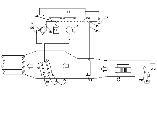
[0065] Introduce the second specific embodiment of the present invention below, Figure 7 It is a schematic diagram of the pipeline connection of the second specific embodiment of the present invention. This embodiment is an improvement on the above first specific embodiment. A bypass channel is provided for the heat exchanger 13 outside the compartment, specifically a three-way is provided at the inlet and outlet of the heat exchanger 13 outside the compartment. Pipe fittings, the second electromagnetic three-way control valve, such as Figure 7 In the middle, a second electromagnetic three-way control valve 28 is set in the pipeline between the heat exchanger 13 outside the compartment and the four-way valve 12, and a three-way pipe is set in the pipeline after the outlet of the heat exchanger 13 outside the compartment. One port of the second electromagnetic three-way control valve 28 is connected to one port of the four-way valve 12, and the other two ports: the first por...

Embodiment approach

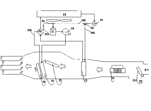
[0067] Introduce the third specific implementation mode of the present invention below, as Figure 8 shown. The difference from the specific implementation described above is that there is no four-way valve in this embodiment, and the manufacturing difficulty of the four-way valve in the automobile air conditioner is relatively large. Therefore, in this embodiment, an electromagnetic three-way control valve and a Solenoid valve combination to replace the four-way valve.

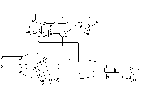
[0068] Specifically, the air conditioning system includes a third electromagnetic three-way control valve 15 arranged between the first heat exchanger 18 and the outside heat exchanger 13, and the third electromagnetic three-way control valve 15 also has an interface connected to the second heat exchanger. In the pipeline between the exchanger 17 and the vapor-liquid separator 11; in addition, on the pipeline between the third electromagnetic three-way control valve 15 and the heat exchanger 13 outside the c...


PUM


Abstract

A car air-conditioning system comprises a compressor, a gas-liquid separator which is located in front of an air inlet of the compressor, a first heat exchanger and a second heat exchanger, a compartment outer heat exchanger and a throttling component. The first heat exchanger and the second heat exchanger are respectively arranged and conduct heating, cooling or demisting on the compartment according to working condition requirements in the compartment. The first heat exchanger is connected with an air outlet of the compressor. The car air-conditioning system comprises a refrigerating mode, a heating mode, a demisting mode and a deicing mode. When moisture is eliminated, wind which is supplied to the compartment dried through the second heat exchanger and then passes the first heat exchanger. The first heat exchanger can choose whether to warm up, and then supplies the wind to the compartment. Therefore, the temperature of the wind which is supplied to the compartment can be chosen, and comfort is improved.

Description

technical field [0001] The invention relates to the technical field of automobile air conditioning, in particular to an electric automobile air conditioning system. Background technique [0002] With the development of low-carbon economy, more stringent requirements are put forward for energy saving and emission reduction. Electric vehicles will become one of the aspects of future automobile development due to their energy-saving and environmental protection features. However, since electric vehicles use batteries as a power source, their air-conditioning systems are also different from the original automotive air-conditioning systems. [0003] Traditional internal combustion engine vehicles can use the waste heat of the internal combustion engine and the heat of the engine exhaust to heat the cabin, while the power of electric vehicles mainly comes from the motor, which lacks the heat of the engine to be used, making it difficult to meet the heating requirements in winter. ...

Claims


Application Information

Patent Timeline
Patent Type & Authority Applications(China)
IPC IPC(8): B60H1/00
Inventor 黄宁杰李雄林
Owner SANHUA HLDG GRP
Why Eureka
Try Eureka