Anti-vibration device

A technology of anti-vibration devices and cylindrical parts, which is applied in the direction of control devices, power devices, jet propulsion devices, etc., can solve problems such as restrictions, and achieve the effect of preventing relative displacement

Inactive Publication Date: 2013-06-19
KURASHIKI KAKO CO LTD
View PDF1 Cites 2 Cited by
  • Summary
  • Abstract
  • Description
  • Claims
  • Application Information

AI Technical Summary

Problems solved by technology

In the swing support method, if a large driving reaction force acts on the engine suspension system, such as when the car accelerates or decelerates sharply, the engine-transmission assembly will swing in a large direction like a pendulum along the front and rear directions of the vehicle body, but because the engine -The lower end o

Method used


Image

  • Anti-vibration device
  • Anti-vibration device
  • Anti-vibration device

Examples


no. 1 approach

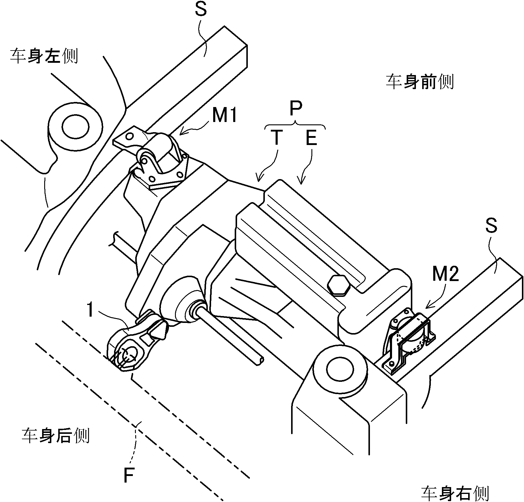
[0051] figure 1 It is a perspective view showing a schematic structure of the automobile engine mount system according to the embodiment. exist figure 1 Among them, the symbol P represents the engine-transmission assembly composed of the engine E and the transmission T in series.

[0052] The engine-transmission assembly P is arranged horizontally in the engine room such that the longitudinal direction of the engine-transmission assembly P coincides with the vehicle width direction. The engine-transmission assembly P is elastically supported with respect to the vehicle side member S by anti-vibration supports M1 and M2 respectively arranged at both ends in the longitudinal direction thereof. The two anti-vibration supports M1, M2 are arranged at positions higher than the main axis of inertia (roll axis) of the engine-transmission assembly P, so that the engine-transmission assembly P can be connected around the two anti-vibration supports. The swing support shafts of the lo...

no. 2 approach

[0071] Next, a torque rod 101 according to a second embodiment of the present invention will be described.

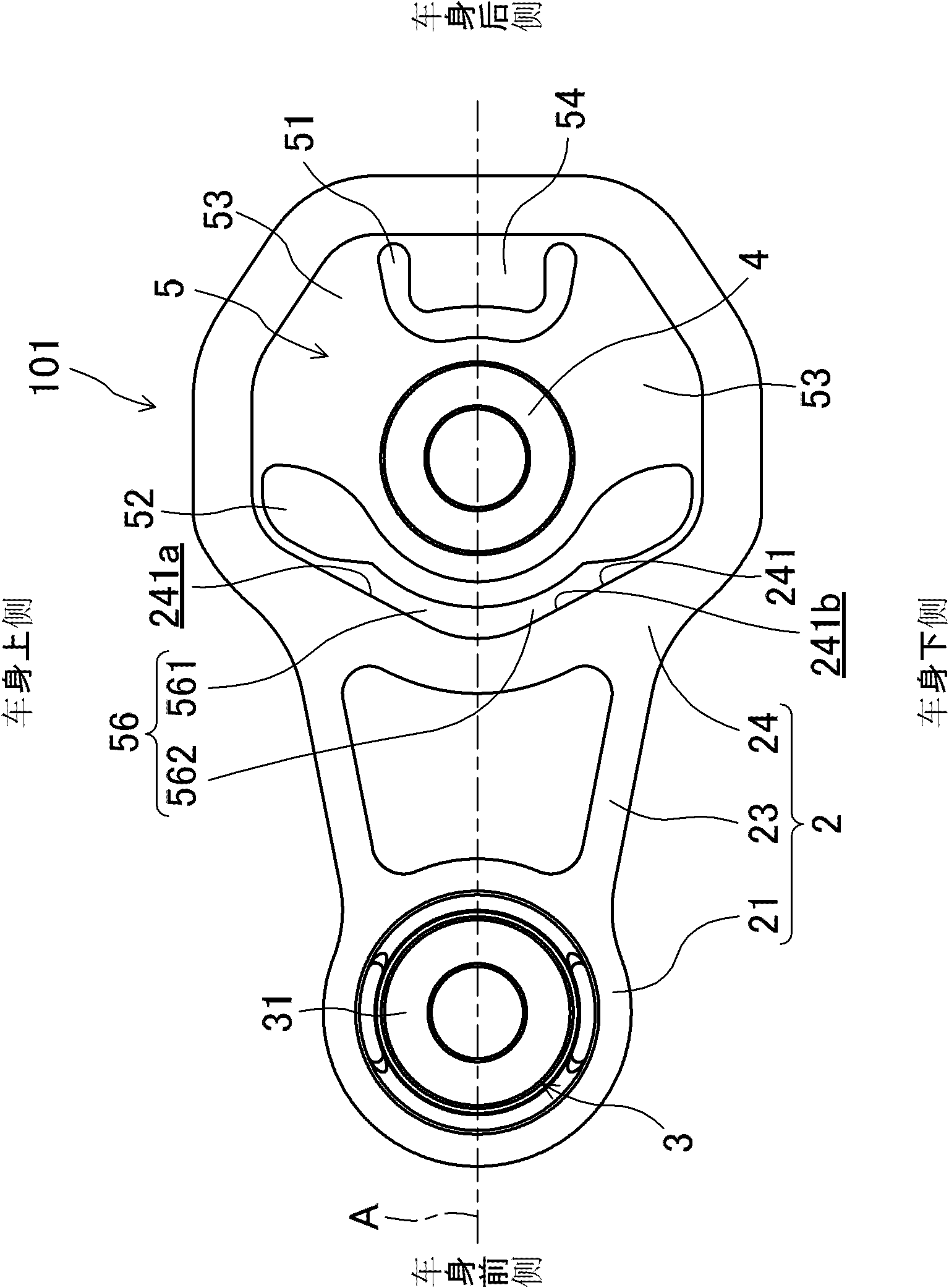
[0072] Such as image 3 As shown, in the torque rod 101 according to the second embodiment, the structures of the second cylindrical portion and the stopper portion are different from those of the first embodiment. Therefore, the same components as those in the first embodiment are denoted by the same reference numerals, descriptions thereof are appropriately omitted, and configurations different from those in the first embodiment are mainly described.

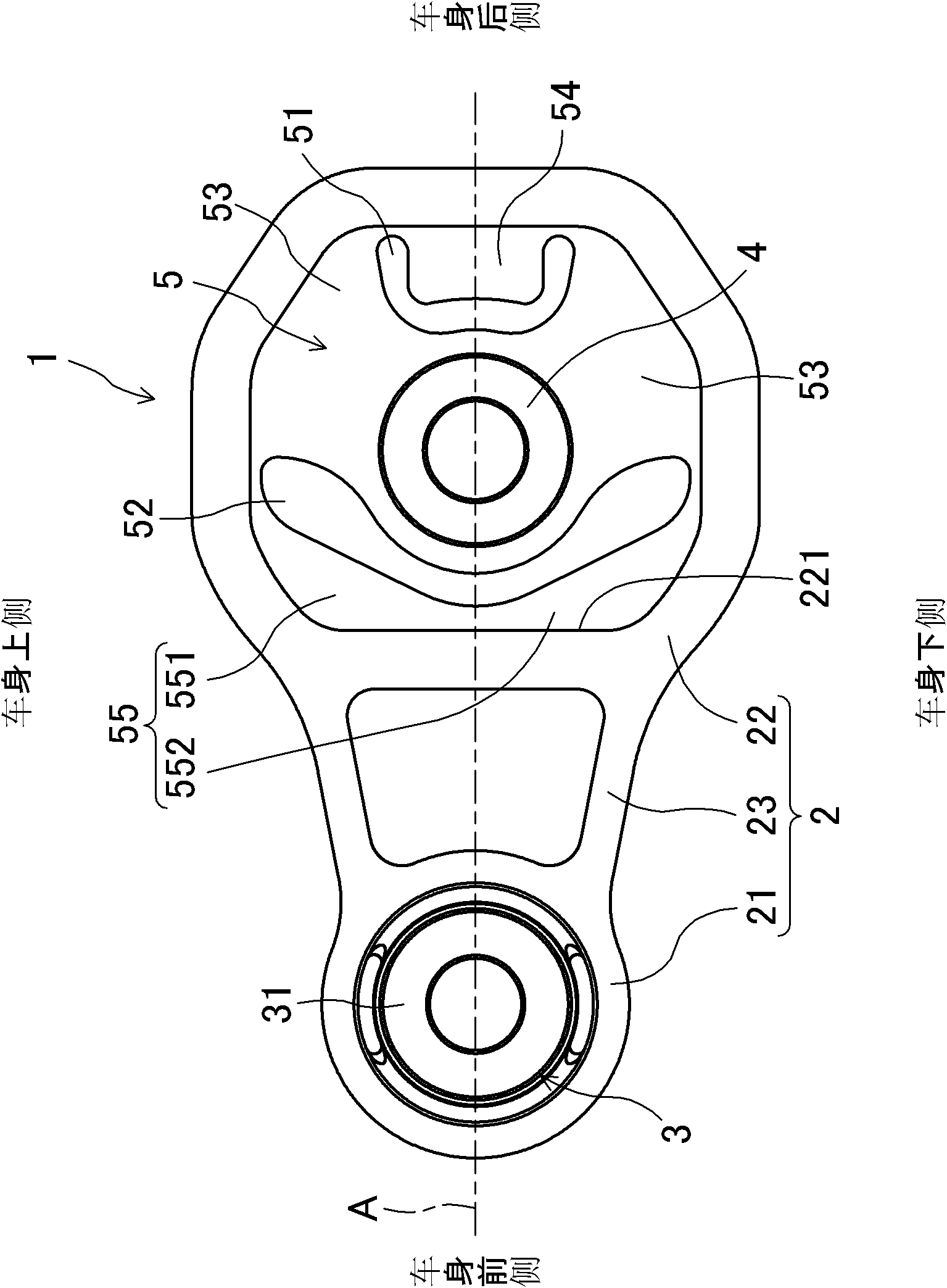
[0073] torque rod 101 with figure 2 Unlike the illustrated torque rod 1 having the vertically flat installation portion 221 , the installation portion 241 of the torque rod 101 has inclined installation surfaces on both upper and lower sides sandwiching the reference axis A, respectively.

[0074] Specifically, the second cylindrical portion 24 is formed so that the cylindrical hole has a heptagonal shape in side vie...


PUM


Abstract

The invention discloses an anti-vibration device. A torque rod comprises a limiting part which is provided with a first guiding portion and a second guiding portion, wherein the first guiding portion inclines relative to the vertical direction of a vehicle body on one of two sides in the vertical direction of the vehicle body, and a reference shaft is arranged between the two sides; and the second guiding portion inclines towards the direction, opposite to the inclining direction of the first guiding portion, relative to the vertical direction of the vehicle body on the other side of the two sides. Therefore, if one side of a second inner tube body deviates from the reference shaft and contacts the limiting part, the side of the second inner tube body moves along the first guiding portion or the second guiding portion and close to and relative to the reference shaft, and the second inner tube body moves onto the reference shaft at last. As a result, the rotation of a support frame is avoided. Therefore, when the anti-vibration device of the vehicle body is combined with an engine-gearbox assembly and other bodies to be supported, relative displacement which exceeds a set maximum stroke can be reliably prevented from happening.

Description

technical field [0001] The present invention relates to an anti-vibration device for connecting a supported body such as an engine-transmission assembly of an automobile and a vehicle body. Background technique [0002] So far, for example, the so-called horizontal installation method is generally adopted in front-engine-front-wheel drive (FF) vehicles, that is, the engine-transmission assembly composed of the engine and the transmission in series is arranged horizontally in the engine room, and The long side direction of the engine-transmission assembly is consistent with the vehicle width direction. As an example of a horizontal mounting method, there is a so-called pendulum mount method, in which vibration-proof supports are used to elastically support both ends of the engine-transmission assembly in the longitudinal direction with respect to the vehicle side beams, and these The two anti-vibration supports are arranged at a position higher than the main axis of inertia ...

Claims


Application Information

Patent Timeline
IPC IPC(8): B60K5/12B60K17/06
Inventor 沟部匡晃三宅和夫
Owner KURASHIKI KAKO CO LTD
Why Eureka
Try Eureka