Filling head for filling containers

A filling and container technology, applied in the field of filling mechanism, can solve problems such as inability to fill, and achieve the effect of compact structure

Active Publication Date: 2013-06-19
KRONES AG
View PDF7 Cites 11 Cited by
  • Summary
  • Abstract
  • Description
  • Claims
  • Application Information

AI Technical Summary

Problems solved by technology

According to the design structure of the above-mentioned liquid level probe, the typical requirement for the conductivity of

Method used


Image

  • Filling head for filling containers
  • Filling head for filling containers
  • Filling head for filling containers

Examples


Embodiment Construction

[0039] Hereinafter, preferred embodiments will be described with reference to the accompanying drawings. Here, identical, similar or identically functioning components are denoted by the same reference numerals, and repeated descriptions of such components are sometimes omitted in the following description to avoid lengthy description.

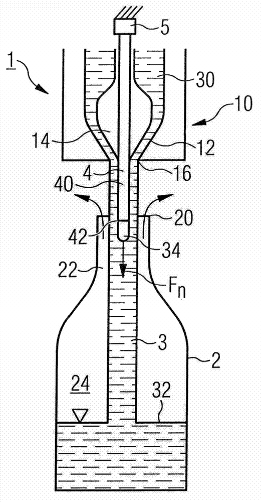
[0040] figure 1 A filling device 1 for filling a bottle-shaped container 2 with a liquid 30 is shown. The filling device 1 comprises a full flow filling part 10 for filling a container 2 with a full flow 3 . To this end, the liquid 30 flows out of the outlet opening 16 arranged substantially centrally on the container mouth 20 and flows in the form of a full liquid flow 3 through the mouth 20 and the neck 22 of the container 2 into the container interior 24 . The gas expelled from the container 2 by the raised liquid level 32 (i.e., for example, the air located in the container cavity 24) can flow into the liquid 30 of the container cavity 2...


PUM


Abstract

The component (1) has a full jet filling element (10) for filling a container (2) in a full jet (3), and a level probe (4) for determining a level of liquid (30) in the container. The level probe(4) is arranged such that the level probe lies below the full jet filling element(10) when the container is filled in the full jet(3).

Description

technical field [0001] The invention relates to a filling mechanism for filling containers, preferably beverage containers, with beverages. Background technique [0002] For filling the container with a liquid, different possibilities for forming the respective filling mechanism are disclosed. As is known in the field of beverage filling, depending on the liquid to be filled, in particular depending on the product to be filled, different filling mechanisms are used which take product-specific properties into account as far as possible. [0003] For example, so-called long tube filling mechanisms are known, where the beverage to be filled in the bottle is injected by means of a tube inserted deep into the bottle. In this way, a submerged filling of the bottles is achieved, which exhibits advantageous filling properties especially for foaming and / or oxygen-sensitive products. [0004] Furthermore, so-called tubeless filling systems are known, where the liquid flows into the ...

Claims


Application Information

Patent Timeline
IPC IPC(8): B67C3/22
CPCB67C3/282B67C2003/2685
Inventor 鲁珀特·梅恩金格尔斯提芬·珀斯尔塞巴斯蒂安·鲍姆加特纳斯提芬·富鲁茨特尔
Owner KRONES AG
Why Eureka
Try Eureka