
Reaction chamber and plasma processing equipment applying the same

A technology of reaction chamber and chamber, which is applied in metal material coating process, gaseous chemical plating, coating, etc., can solve the problems of inability to adjust temperature and poor adjustability of process parameters, and achieve the effect of improving adjustability

Active Publication Date: 2013-06-19
BEIJING NAURA MICROELECTRONICS EQUIP CO LTD
View PDF4 Cites 6 Cited by
  • Summary
  • Abstract
  • Description
  • Claims
  • Application Information

AI Technical Summary

Problems solved by technology

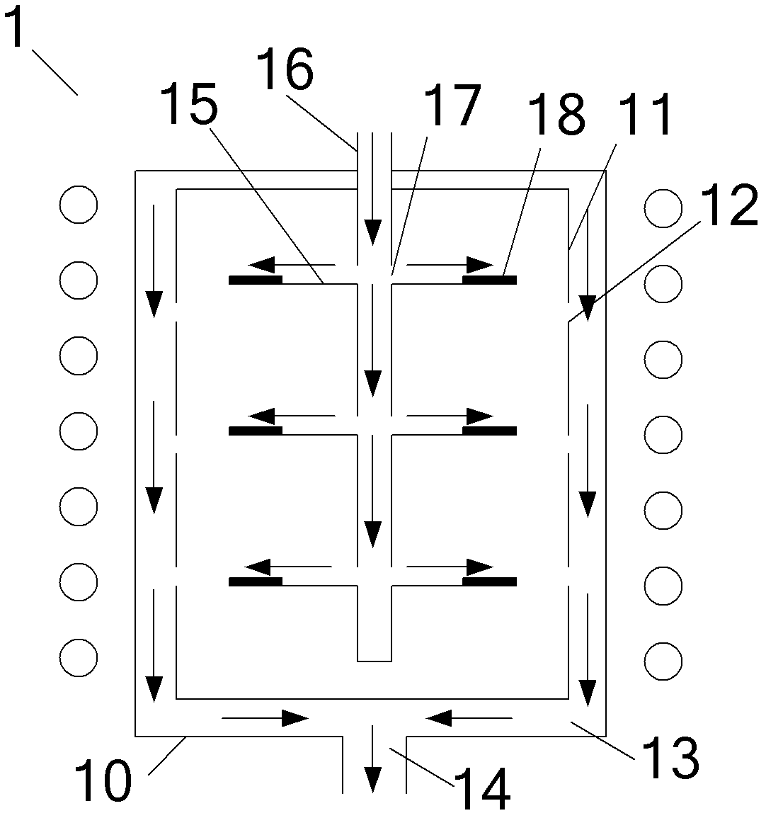
[0004] In actual use, due to the fixed size of the vent hole 12, the temperature of the processed workpiece 18 cannot be adjusted by means of the vent hole 12, which makes the existing MOCVD equipment poor in adjustability to process parameters

Method used


Image

  • Reaction chamber and plasma processing equipment applying the same
  • Reaction chamber and plasma processing equipment applying the same
  • Reaction chamber and plasma processing equipment applying the same

Examples


Embodiment 1

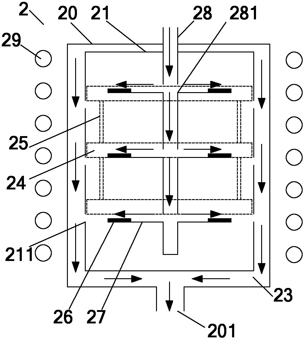
[0029] Figure 2a A schematic diagram of the structure of the reaction chamber provided by the present invention. see Figure 2a , the reaction chamber 2 includes an outer chamber 20 and an inner chamber 21 of a cylindrical structure and a gas delivery pipe 28, wherein an induction coil 29 is arranged on the outside of the outer chamber 20, and it is connected to an AC power supply (not shown in the figure) ) connection for heating the inside of the outer chamber 20; the inner chamber 21 is arranged in the outer chamber 20, thereby forming a gas channel 23 for gas flow between the inner chamber 21 and the outer chamber 20, and the gas The channel 23 communicates with the exhaust channel 201 arranged at the bottom of the outer chamber 20, so that the gas in the gas channel 23 can be gathered to the exhaust channel 201 to be discharged; Three rows of exhaust ports 211 are arranged in the axial direction, and each row of exhaust ports 211 is evenly distributed in the circumfere...

Embodiment 2

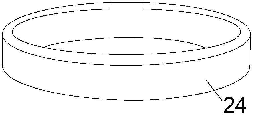
[0041] Figure 3a It is a schematic diagram of the shielding plate according to the second embodiment of the present invention. see Figure 3a , in this embodiment, the baffle plate 24 is a ring that is close to the wall of the cylindrical inner chamber 21 and is provided with a through hole 241 having the same size as the exhaust port 211 . The driving device is a rotary motor for driving the shielding plate 24 to rotate around the axis of the inner chamber 21 . When in use, the shielding plate 24 rotates clockwise or counterclockwise under the drive of the rotating motor. When the through hole 241 is completely overlapped with the exhaust port 211, the exhaust port 211 is the largest. At this time, the inner chamber 21 emits the most heat from the exhaust port 211, so that the heat loss rate of the reaction chamber 2 is the largest; In the process of interlacing the through holes 241 and the exhaust ports 211, the overlapping degree of the through holes 241 and the exhaus...


PUM


Abstract

Provided are a reaction chamber and plasma processing equipment applying the same. The reaction chamber comprises an outer chamber, an inner chamber and a gas delivery tube, wherein the inner chamber is arranged in the outer chamber, a gas passage is formed between the inner chamber and the outer chamber, the gas passage is communicated with an exhaust passage of the outer chamber, the gas delivery tube is arranged in the inner chamber, a plurality of gas inlets for delivering process gas to the inner chamber is arranged on the gas delivery tube and an exhaust port is arranged on the chamber wall of the inner chamber. An exhaust port adjustment unit is arranged at the position of the exhaust port to adjust the distribution of temperature in the inner chamber and to further improve the adjustability of the plasma processing equipment.

Description

technical field [0001] The invention relates to the technical field of microelectronic processing, in particular to a reaction chamber and plasma processing equipment using the reaction chamber. Background technique [0002] Metal Organic Chemical Vapor Deposition (hereinafter referred to as MOCVD) technology is a technology that thermally decomposes organic metal raw material gases, hydrogenated gases or halogenated gases to obtain thin films. Excellent and other advantages and is widely used in the preparation of various thin films [0003] figure 1 It is a simplified structural diagram of an existing MOCVD device. see figure 1 , the MOCVD apparatus comprises a reaction chamber 1, the reaction chamber 1 includes an outer chamber 10 and an inner chamber 11 arranged inside the outer chamber 10, and the outer diameter of the inner chamber 11 is smaller than the inner diameter of the outer chamber 10, so that in the outer chamber A gas passage 13 for gas flow is formed bet...

Claims


Application Information

Patent Timeline
IPC IPC(8): C23C16/52
Inventor 王一帆
Owner BEIJING NAURA MICROELECTRONICS EQUIP CO LTD
Learn More