
Radiator

A technology for radiators and heat pipes, applied in the direction of indirect heat exchangers, heat exchanger types, machines/engines, etc., can solve problems such as radiator damage

Inactive Publication Date: 2013-06-19
GUANGXI LIUGONG MASCH CO LTD
View PDF9 Cites 2 Cited by
  • Summary
  • Abstract
  • Description
  • Claims
  • Application Information

AI Technical Summary

Problems solved by technology

[0003] The object of the present invention is to provide a heat dissipation tube in the radiator core that is not easy to be damaged by foreign matter in the radiator core, aiming at the defect that the heat dissipation tube in the radiator core of the existing radiator is easily broken by the foreign matter hit by the heat dissipation fan, resulting in damage to the radiator. cracked radiator

Method used


Image

  • Radiator
  • Radiator
  • Radiator

Examples


Embodiment Construction

[0016] The specific implementation will be described below in conjunction with the accompanying drawings.

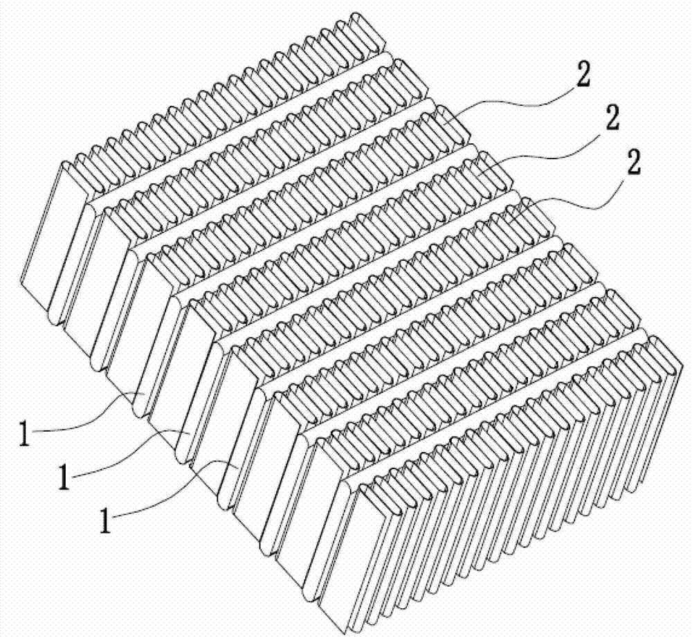
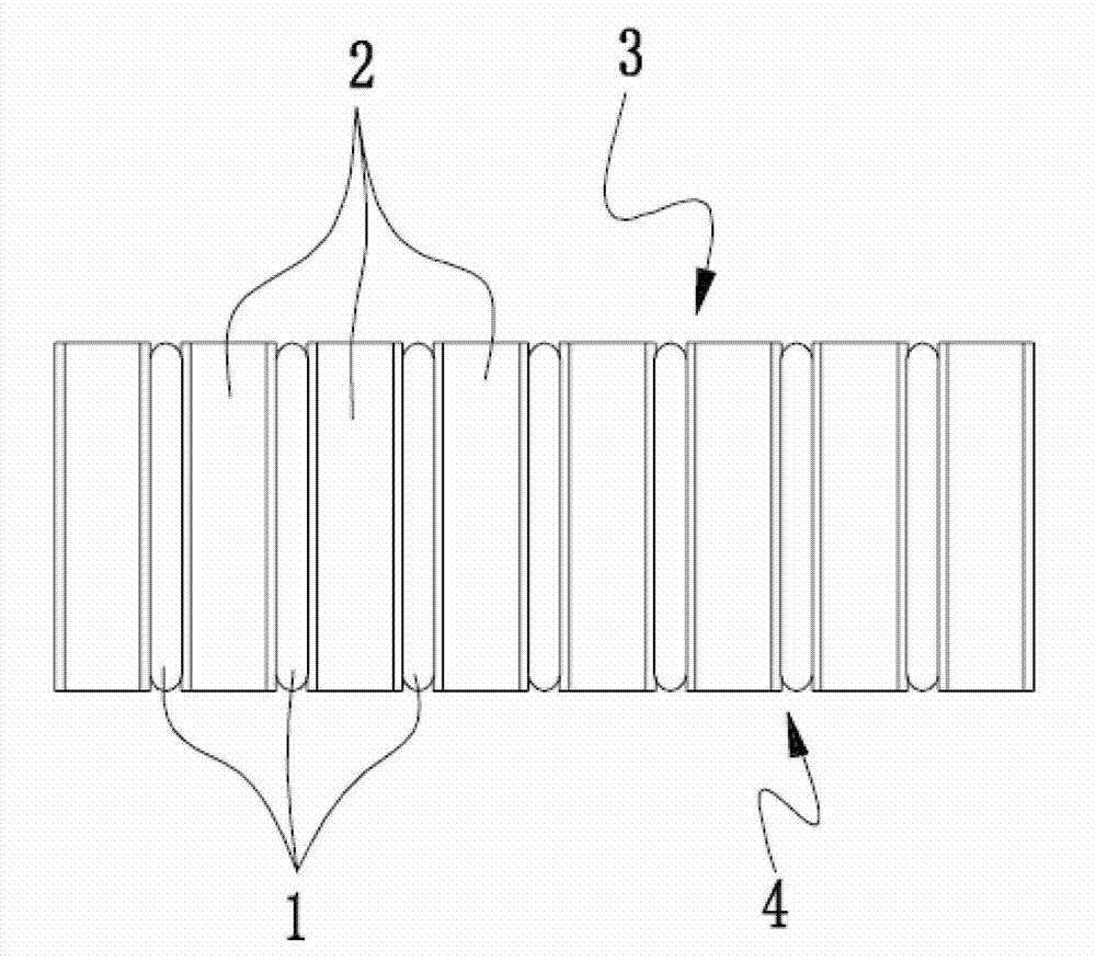
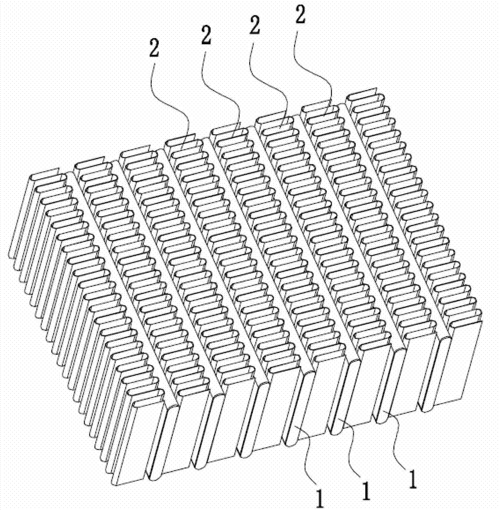
[0017] Such as image 3 Figure 4 As shown, in this embodiment, the radiator includes a radiator core, and the radiator core includes several heat dissipation pipes arranged vertically at intervals. The heat dissipation pipes 1 are flat and are arranged between two adjacent heat dissipation pipes. There are radiating fins 2, and the radiating fins 2 are in contact with the radiating pipe 1 on both sides thereof, and the upper and lower ends of the radiating pipe 1 communicate with the upper water chamber and the lower water chamber of the radiator respectively. The heat sink 2 is bent into a wave shape by a metal sheet. On the windward side 4 of the radiator core, the heat sink 2 protrudes from the windward side plane D1 of the heat sink, that is, the windward side D2 of the heat sink protrudes from the windward side plane D1 of the heat sink, and the protrusion distan...


PUM


Abstract

The invention relates to a radiator. The radiator overcomes the defects that a radiating tube in a radiator core of an existing radiator is easily destroyed by foreign bodies which are struck by a cooling fan and the radiator is damaged. The radiator comprises a radiator core and a plurality of radiating tubes which are arrayed in parallel and at intervals. Radiating fins are arranged between adjacent two radiating tubes, the both sides of the radiating fins are in contact connection with the radiating tubes, and the radiating fins on a windward side of the radiator core protrude out of a windward side plane of the radiating tubes. According to the radiator, due to the fact that on the windward side of the radiator core, the radiating fins protrude out of the windward side plane of the radiating tubes, the radiating fins can effectively block the foreign bodies such as rubble which is struck by the cooling fan, and avoid the situation that the radiating tubes are hit by the foreign bodies and are damaged.

Description

technical field [0001] The invention relates to a radiator, in particular to an air-cooled liquid radiator. Background technique [0002] The radiator is usually used as a necessary heat dissipation device for internal combustion equipment such as automobiles and construction machinery. Cooling water or coolant flows from the engine through the radiator through the pipeline, and then flows back to the engine after being cooled by the radiator, so as to maintain the engine at a constant temperature. Reasonable working temperature. The radiator includes a radiator core. The radiator core consists of several parallel and spaced heat dissipation pipes. A heat dissipation fin is arranged between two adjacent heat dissipation pipes. The heat dissipation fins correspond to the two sides respectively. The heat sink is contacted and connected, and the heat sink is usually bent into a wave form by a metal sheet. Since the heat dissipation pipe 1 needs to dissipate heat with the help...

Claims


Application Information

Patent Timeline
Patent Type & Authority Applications(China)
IPC IPC(8): F01P11/00F28D1/053
Inventor 徐冲冯昌兴吴奕万韦秀梅李群华
Owner GUANGXI LIUGONG MASCH CO LTD
Learn More