Impeller for residual heat removal pump
A technology for exhausting pumps and impellers of waste heat, applied to components, pumps, pump components, etc. of pumping devices used for elastic fluids, to achieve the effect of head reduction
- Summary
- Abstract
- Description
- Claims
- Application Information
AI Technical Summary
Problems solved by technology
Method used
Image
Examples
Embodiment 1
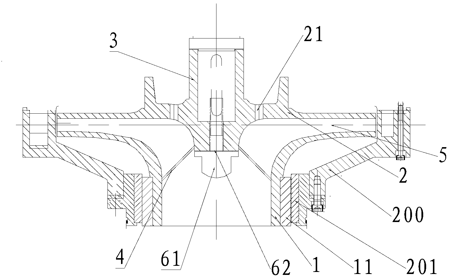
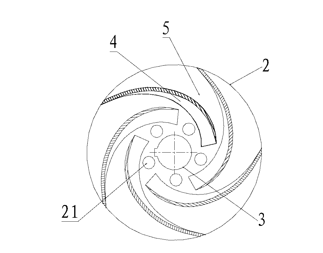
[0024] see figure 2 , in this embodiment, five blades 4 are arranged between the top surface of the front cover plate 1 of the impeller and the bottom surface of the rear cover plate 2, the blades 4 are curved into an arc shape, and arranged around the circumference of the hub 3 in the counterclockwise direction, and Extend to the edge of the rear cover 2. The blade 4 extends to the edge of the rear cover 2 in order to prevent the reactor coolant in the adjacent impeller flow channel 5 from colliding, resulting in cavitation of the impeller, and also to further ensure the stability of the impeller rotation center and further balance the pump shaft 100 Axial force. The blades 4 are bent into an arc and arranged counterclockwise around the circumference of the hub 3 so that the direction in which the blades 4 are arranged around the circumference of the hub 3 is opposite to the direction in which the pump shaft 100 rotates, reducing the hydraulic loss of the reactor coolant in...
Embodiment 2
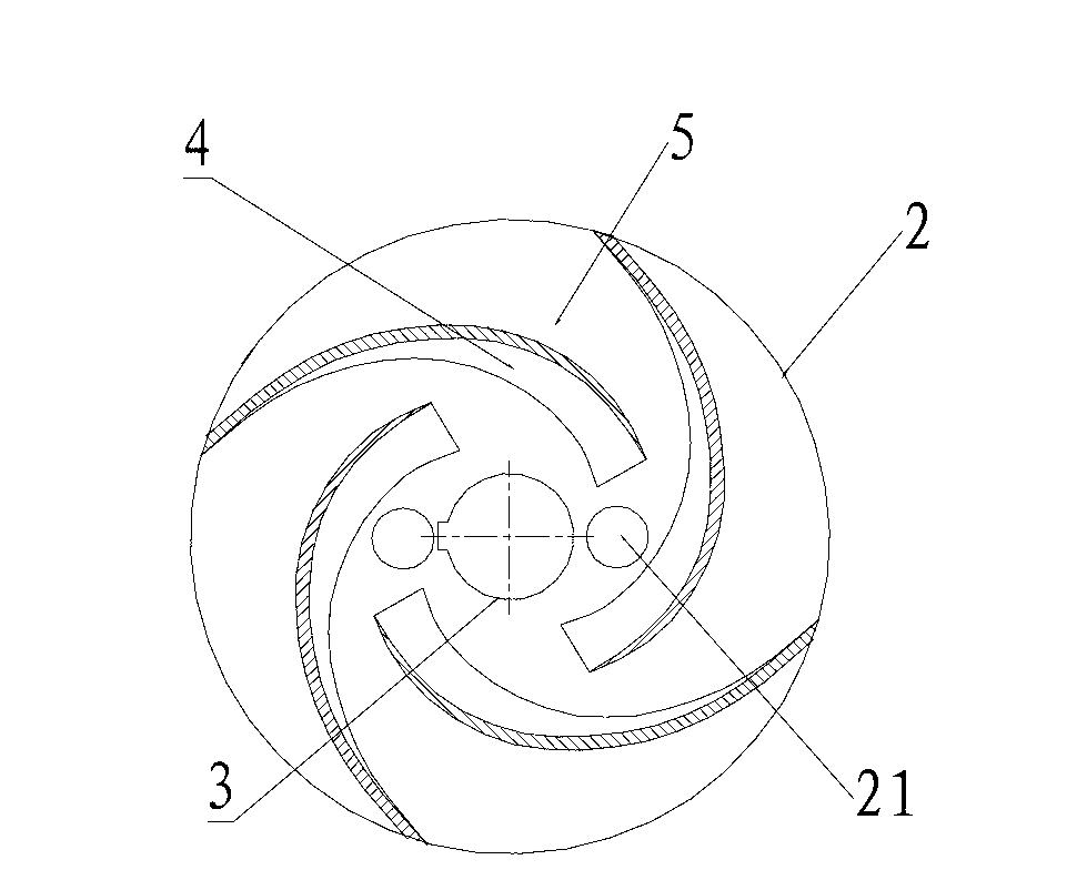
[0026] see image 3 , In this embodiment, four blades 4 are arranged between the top surface of the front cover 1 and the bottom surface of the rear cover 2 of the impeller. The blades 4 are bent into an arc and arranged counterclockwise around the circumference of the hub 3 in order to make the direction in which the blades 4 are arranged around the circumference of the hub 3 opposite to the direction in which the pump shaft 100 rotates, reducing the hydraulic loss of the reactor coolant inside the impeller, further Enhance the anti-cavitation performance of the impeller and prolong the service life of the impeller. In this embodiment, the number of balanced through holes 21 is two, that is, the number N of vanes 4 is twice the number M of balanced through holes 21 . In this embodiment, compared with the impeller that does not set the balance through hole 21, but only extends the blade 4 to the edge of the rear cover plate 2, the cavitation of the impeller is greatly reduced...
Embodiment 3
[0028] see Figure 4 , In this embodiment, four blades 4 are arranged between the top surface of the front cover plate 1 and the bottom surface of the rear cover plate 2 of the impeller. The blades 4 are linear and arranged radially around the circumference of the hub 3 . In this embodiment, the number of balanced through holes 21 is four, that is, the number N of vanes 4 is twice the number M of balanced through holes 21 . In this embodiment, compared with the impeller that does not set the balance through hole 21, but only extends the blade 4 to the edge of the rear cover plate 2, the cavitation of the impeller is greatly reduced, and the service life is prolonged by 25%. The impeller with a balanced through hole 21 without extending the vane 4 to the edge of the rear cover 2, the axial force on the pump shaft 100 is significantly reduced, and the bearing (not shown) sleeved on the pump shaft 100 is effectively protected. The service life of the bearing was extended by 18%....
PUM
 Abstract
Description
Claims
Application Information
 - R&D
- Intellectual Property
- Life Sciences
- Materials
- Tech Scout
- Unparalleled Data Quality
- Higher Quality Content
- 60% Fewer Hallucinations
Browse by: Latest US Patents, China's latest patents, Technical Efficacy Thesaurus, Application Domain, Technology Topic, Popular Technical Reports.
© 2025 PatSnap. All rights reserved.Legal|Privacy policy|Modern Slavery Act Transparency Statement|Sitemap|About US| Contact US: help@patsnap.com


